Substrate heating equipment and substrate heating method

A technology for heating devices and substrates, which is applied in the processing of photosensitive materials, optics, instruments, etc., can solve the problems of low effective sensitivity, low productivity and long exposure time of chemically enhanced resists

Inactive Publication Date: 2007-06-20
TOKYO ELECTRON LTD +1
View PDF2 Cites 13 Cited by
  • Summary
  • Abstract
  • Description
  • Claims
  • Application Information

AI Technical Summary

Problems solved by technology

Therefore, electron beam direct write exposure is actually difficult
[0012] As mentioned above, chemically amplified resists have lower effective sensitivity and longer exposure time in electron beam direct write exposure, and are different from those using KrF excimer laser (λ=248nm) or ArF excimer laser (λ=193nm). ) compared with the exposure performed by the stepper (stepper, a system that reduces the projection step length and repeats the exposure), the productivity is extremely low

Method used


Image

  • Substrate heating equipment and substrate heating method
  • Substrate heating equipment and substrate heating method
  • Substrate heating equipment and substrate heating method

Examples


Embodiment 1

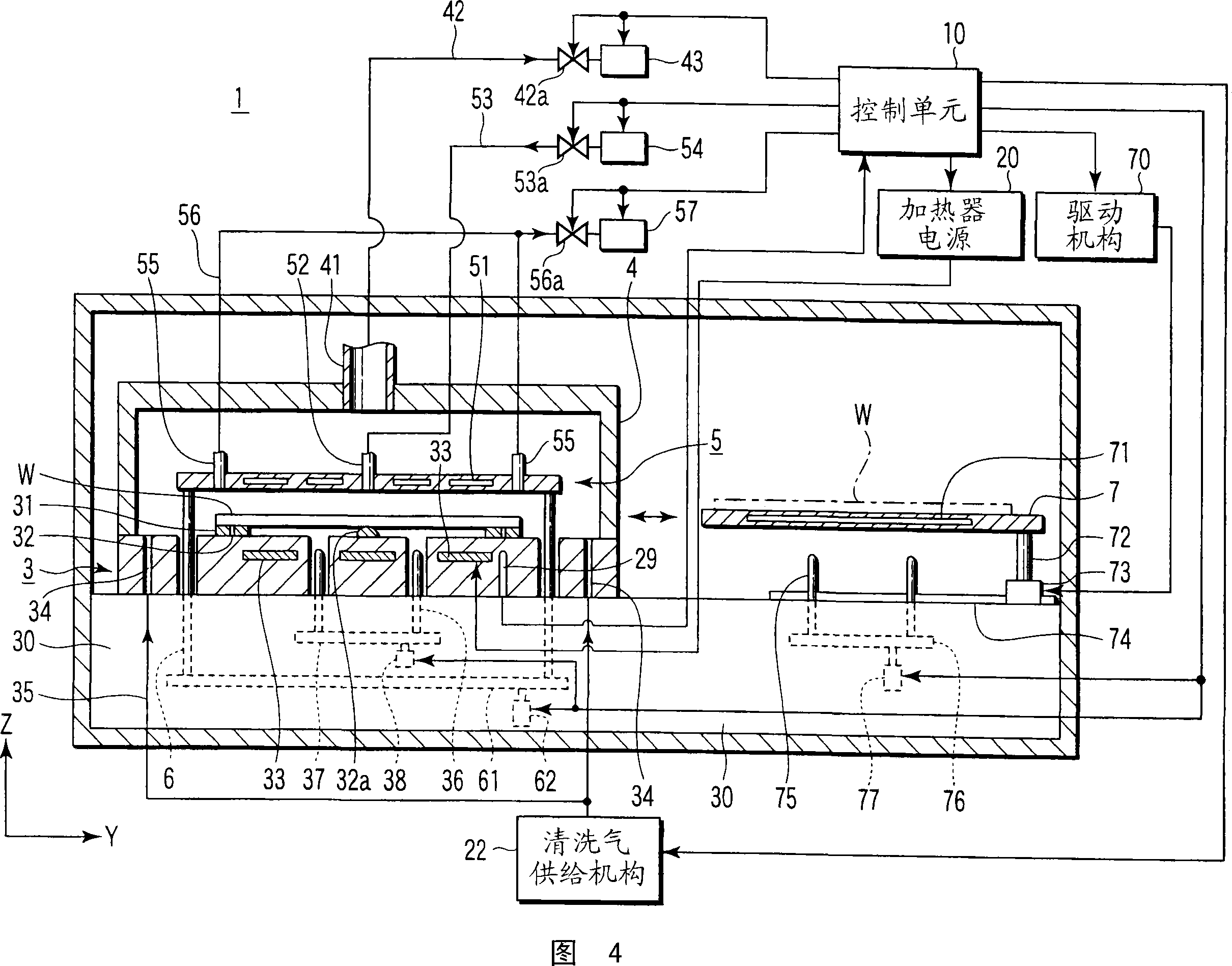
[0055] The substrate heating apparatus and method according to the first embodiment of the present invention will be described below with reference to FIGS. 4-8 . In this embodiment, a description will be made based on an example of a heating-cooling unit formed by combining a cooling unit with a heating unit as the substrate heating apparatus of the present invention. However, the cooling unit can also be provided independently of the heating unit.

[0056] The heating unit and the cooling unit are arranged in the housing of the heating-cooling device 1 as shown in FIGS. 4 and 5 . The heating unit is arranged on the left side in the drawing, and has a mounting table 3 with a heater 33 buried inside, a cover unit 4 and a fluid control board 5 . The cooling unit is arranged on the right side in the figure, and has a cooling plate 7 containing a coolant 71 .

[0057] The mounting table 3 on which the wafer W is horizontally arranged is arranged on the base 30 . The inside of ...

Embodiment 2

[0102] Next, a second embodiment will be described with reference to FIGS. 9 and 10 . Description of the same components as those in the first embodiment will be omitted.

[0103] The unit 1A of the second embodiment has a fluid supply unit 54A to supply mist or steam containing glycerin to the gap between the wafer W and the fluid control plate 5 . The fluid supply unit 54A includes a first storage tank for glycerin, a second storage tank for solvent, a mass flow controller (MFC), a mixer, and a vaporizer. The vaporizer has spray nozzles to mechanically or physically spray the glycerin and solvent mixture as fine droplets. One of ethanol and an organic solvent can be used as the solvent.

[0104] The internal flow path of the fluid supply unit 54A is connected to the supply port 52A of the fluid control plate 5 through the flexible tube 53 . The flexible tube has a valve 53a. The control unit 10A controls the fluid supply unit 54A, the valve 53a, the heaters 33 and 51, an...

Embodiment 3

[0113] Next, a substrate heating apparatus of a third embodiment will be described with reference to FIG. 11 . The description of the same parts as in the previous embodiment will be omitted.

[0114] The substrate heating apparatus 1B of the present embodiment is basically the same as the apparatus 1 of the first embodiment except that it has means for supplying the wafer W with a cooling liquid that is mixed with a cleaning liquid for cleaning the wafer W (as a cleaning liquid). Allow. In this device 1B, the supply pipe 53 connected to the fluid supply port 52 is branched halfway, and connected to the cooling liquid supply source 8 (for example, pure water whose temperature has been adjusted), so that by means of the three-way pipe operated by the control unit 10B, One of the resist reforming fluid and the cooling water is supplied to the upper surface of the wafer W through the fluid supply port 52 through the valve 81 .

[0115] A method of heating a wafer W through a PE...


PUM

PropertyMeasurementUnit
thicknessaaaaaaaaaa
thicknessaaaaaaaaaa

Abstract

Substrate heating equipment performs heat treatment after exposure but prior to development to a substrate having a chemical-amplification resist film. The substrate heating equipment is provided with a placing table whereupon the substrate is placed substantially horizontal, with the resist film on top, a fluid supplying mechanism for supplying the substrate with glycerin, and a heating mechanism for heating the substrate on the placing table under the condition where the glycerin is brought into contact with the resist film. In the substrate heating equipment, the substrate on the placing table is heated under the condition where the glycerin is brought into contact with the resist film.

Description

technical field [0001] The present invention relates to a substrate heating apparatus and method for coating a substrate with a chemically amplified resist and baking the resist-coated film after exposure and before development (post-exposure bake; PEB). Background technique [0002] A system used in a photolithography process of a semiconductor device includes a coating-developing unit in an exposure unit. Chemically amplified resists are mainly used in coating-developing devices when the line width of circuit patterns reaches the deep sub-micron range. Chemically amplified resists contain acid generators to generate acid when heated. When heat treatment called PEB (Post Exposure Baking) is performed, acid diffuses in the exposed area, and an acid-catalyzed reaction occurs. [0003] 1A-1C are schematic diagrams showing exposure, heating and development by using a positive chemically amplified resist. First, a wafer W coated with a thin film of resist R is subjected to pa...

Claims


Application Information

Patent Timeline
Patent Type & Authority Applications(China)
IPC IPC(8): H01L21/027G03F7/38G03F7/039
CPCH01L21/67748H01L21/67109G03F7/38
Inventor 西孝典北野高广奥村胜弥
Owner TOKYO ELECTRON LTD
Why Eureka
Try Eureka