Sealing device

A sealing device and coating technology, applied in the direction of engine sealing, machine/engine, leakage prevention, etc., can solve the problem of low adhesion strength of the base material, and achieve the effect of preventing fluid leakage

Inactive Publication Date: 2007-06-27
KK TOSHIBA
View PDF0 Cites 17 Cited by
  • Summary
  • Abstract
  • Description
  • Claims
  • Application Information

AI Technical Summary

Problems solved by technology

However, the problem caused by this wear-resistant layer is that the adhesion strength to the base material is very low

Method used


Image

  • Sealing device
  • Sealing device
  • Sealing device

Examples


Embodiment Construction

[0041] Embodiments of the sealing device of the present invention will be described below with reference to the accompanying drawings.

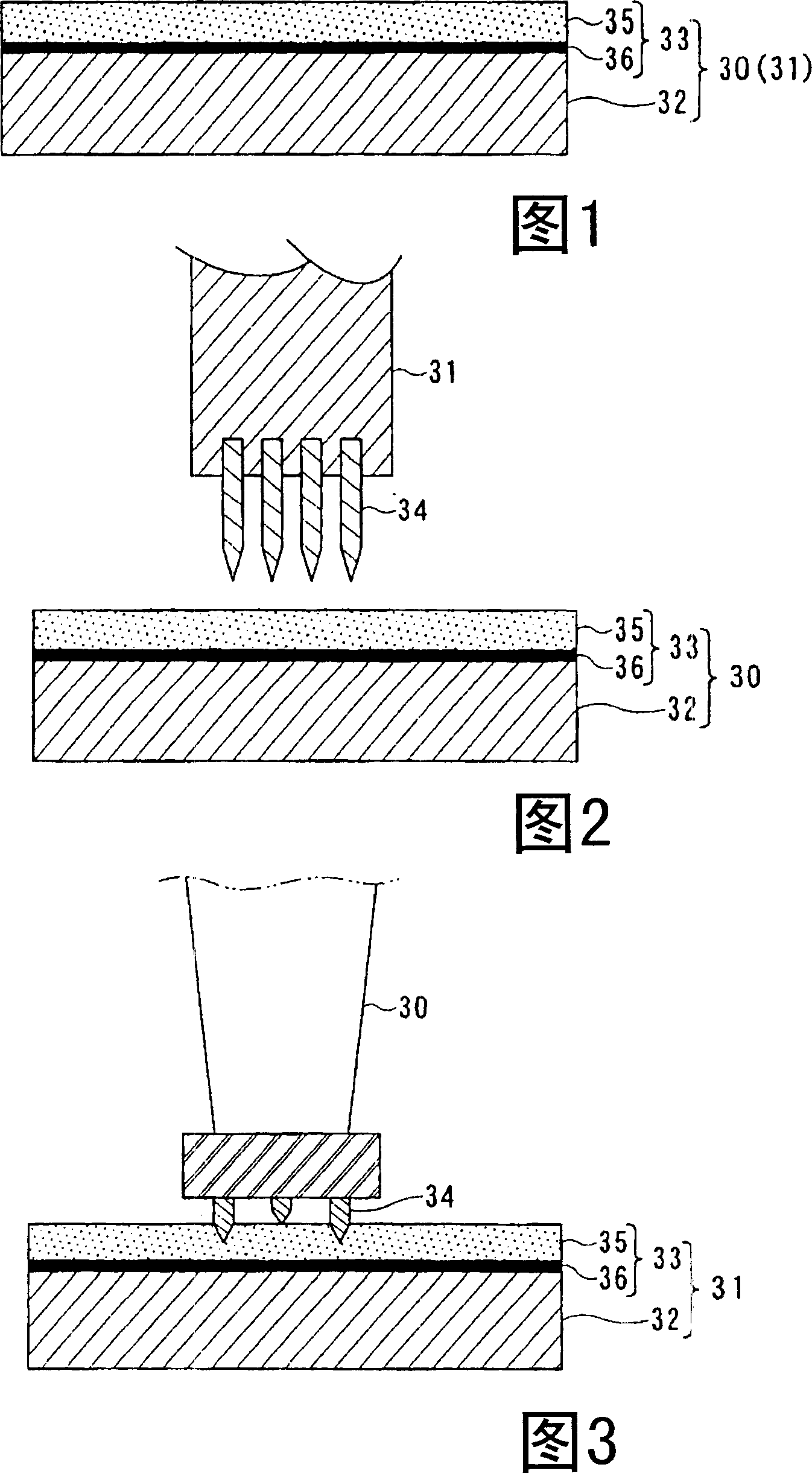
[0042] First, referring to FIG. 1 showing a sealing device according to an embodiment of the present invention, this sealing device is applied to a fluid machine having a rotating part 31 and a stationary (or fixed) part 30, wherein the rotating part 31 is, for example, a turbine rotor and a turbine The movable vanes, the stationary part 30 are for example inner and outer diaphragm rings supporting the turbine nozzle. The coating layer 33 is formed on the base material 32 of either the rotating part 31 or the stationary part 30 . The coating 33 includes a wear-resistant layer (upper layer) 35 and an adhesive layer (lower layer) 36 as a binder (bonding agent).

[0043] In particular, as shown in FIG. 2 , the cover of the movable blade of the turbine is an example of the rotating portion 31 and is provided with sealing fins 34 . The outer rin...


PUM


Abstract

A sealing device by which the leakage of fluid is further reduced by securely maintaining the adhesion between a base material and an abradable layer and further strengthening the prevention of fluid leakage is provided. The sealing device according to the present invention includes seal strips provided to either one of a rotating portion or a stationary portion forming a gap therebetween; and a coating layer provided to a base material of the rotating portion or the stationary portion so that the coating layer faces the seal strips. The coating layer is composed of an abradable layer and a bond coat layer.

Description

technical field [0001] The present invention relates to a sealing arrangement for significantly reducing fluid leakage from, for example, gaps between stationary and rotating parts in fluid machines such as steam turbines or gas turbines. Background technique [0002] Generally, the operating efficiency of a steam or gas turbine used in a power plant is affected by the amount of fluid (torque) used to drive rotation of, for example, turbine blades to generate electricity. That is, the performance of a turbine depends on sealing techniques used to reduce the amount of fluid leakage from the gap between the stationary (or stationary) and rotating parts of the turbine. [0003] Therefore, sealing technology that controls fluids that are not used for power generation is considered an important technology to improve the performance of turbines. [0004] Figure 4 shows a typical structure of a steam turbine, where the sealing technology is considered to be an important technology...

Claims


Application Information

Patent Timeline
Patent Type & Authority Applications(China)
IPC IPC(8): F16J15/447F01D11/04
CPCF16J15/445F16J15/16F16J15/50
Inventor 上村健司佐佐木隆榊田均津田阳一浅井知
Owner KK TOSHIBA
Why Eureka
Try Eureka