Heat radiation module and its heat pipe

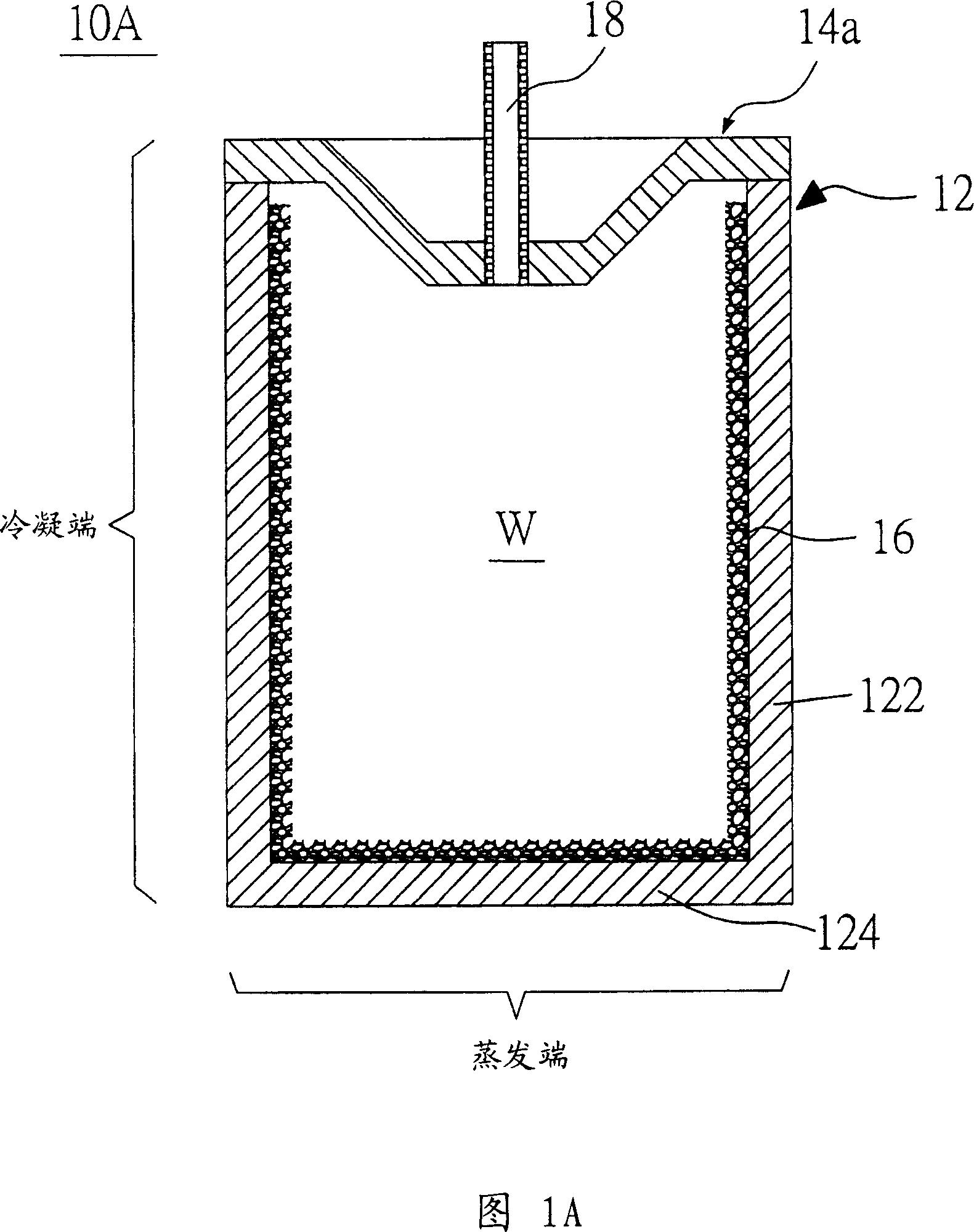
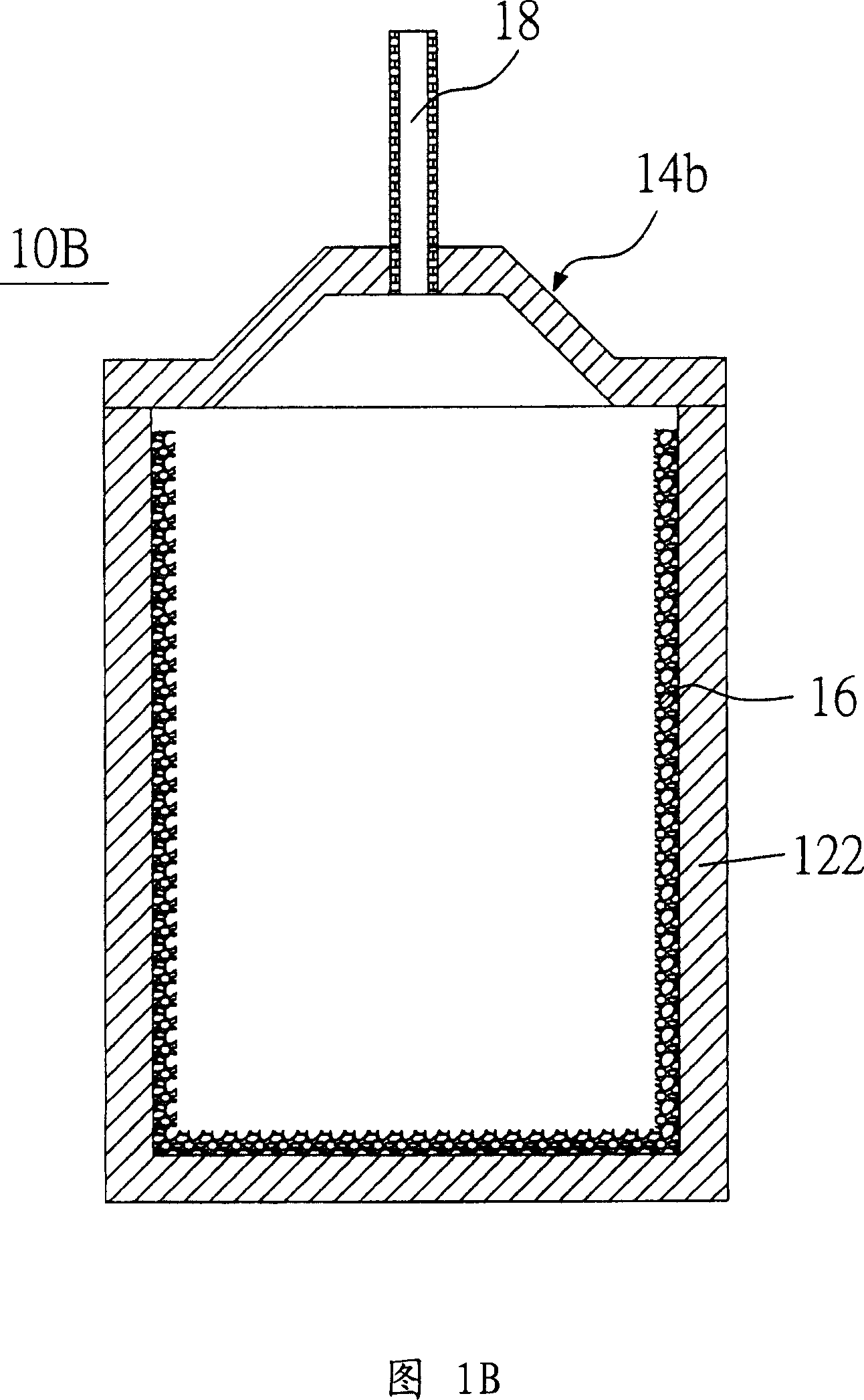
A heat dissipation module and heat pipe technology, applied in indirect heat exchangers, lighting and heating equipment, cooling/ventilation/heating transformation, etc., can solve the problem of increasing the volume of the heat pipe 10B

Active Publication Date: 2007-06-27
DELTA ELECTRONICS INC
View PDF0 Cites 14 Cited by
  • Summary
  • Abstract
  • Description
  • Claims
  • Application Information

AI Technical Summary

Problems solved by technology

However, the effect of only using the bell-shaped upper cover 14b as a guide is limited, and this bell-shaped upper cover 14b makes the water injection pipe 18 installed outside it more protruding outwards, resulting in the overall heat pipe 10B The occupied volume increases, and if the col

Method used


Image

  • Heat radiation module and its heat pipe
  • Heat radiation module and its heat pipe
  • Heat radiation module and its heat pipe

Examples


Embodiment Construction

[0042] Embodiments of the heat dissipation module and the heat pipe thereof according to the present invention will be described below with reference to related drawings.

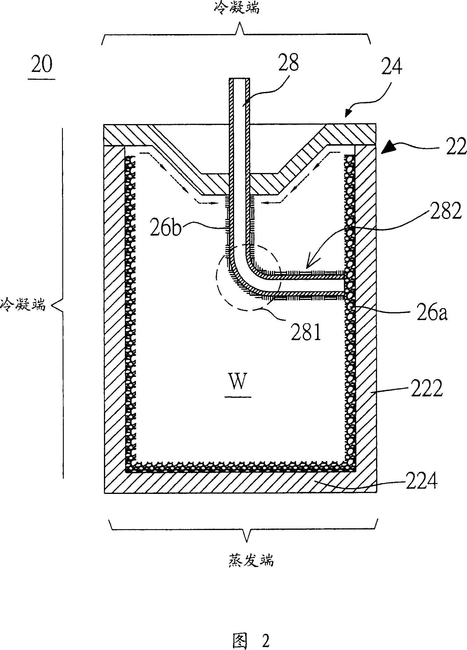
[0043] Please refer to FIG. 2 , which is a schematic diagram of a columnar heat pipe according to a preferred embodiment of the present invention. In FIG. 2 , the columnar heat pipe 20 includes a heat pipe body 22 , an upper cover 24 , a first capillary structure 26 a , a second capillary structure 26 b and a working fluid W filled inside the heat pipe 20 . The heat pipe body 22 has a bottom 224 and a side wall 222 surrounding the bottom 224, and the side wall 222 and the bottom 224 are integrally formed on the heat pipe body 22, or the side wall 222 and the bottom 224 can also be two The components are separated from each other, and the two components are combined to form the heat pipe body 22 .

[0044] On the inner wall of the heat pipe body 22 (that is, on the inner surface of the side wall portion 222...


PUM


Abstract

The heat elimination module includes heat pipe and at least one heat elimination fin. Being setup outside heat pipe, heat elimination fins are connected to main body of heat pipe. Heat pipe includes main body of heat pipe, upper cover, first and second capillary structures and working fluid. Main body of heat pipe possesses a base, and a sidewall setup around the base. An enclosed space is formed when the upper cover is combined with main body of heat pipe. Upper cover is penetrated by a hollow tube with one end being extended inside heat pipe. First capillary structure is setup on inner surface of base of main body of heat pipe, and second capillary structure is connected to body of hollow tube. Being contacted to first capillary structure, second capillary structure makes working fluid condensed on upper cover possible along hollow tube to enter to second capillary structure and flow to first capillary structure.

Description

technical field [0001] The invention relates to a heat dissipation module, in particular to a heat dissipation module with high-efficiency heat pipes. Background technique [0002] With the advancement of technology, the number of transistors per unit area of ​​electronic components is increasing, resulting in an increase in heat generation during operation. On the other hand, the operating frequency of electronic components is also getting higher and higher, and the heat (switch loss) caused by the on / off (on / off) conversion during transistor operation is also the reason for the increase in the heat generation of electronic components. If the heat is not handled properly, the computing speed of the chip will be reduced, and in severe cases, the life of the chip may even be affected. In order to enhance the heat dissipation effect of electronic components, most of the current practices are to use a heat sink to dissipate the heat at the heat source, and dissipate the heat t...

Claims


Application Information

Patent Timeline
IPC IPC(8): F28D15/04H05K7/20
Inventor 庄明德王宏洲念裕贤林祺逢陈锦明
Owner DELTA ELECTRONICS INC
Why Eureka
Try Eureka