Bearing arrangement of sewing machine

A sewing machine and bearing technology, applied in the direction of sewing machine components, sewing equipment, engine lubrication, etc., to achieve smooth rotation, improve durability, and maintain the effect of lubricating performance

Inactive Publication Date: 2007-07-04
BROTHER KOGYO KK
View PDF1 Cites 14 Cited by
  • Summary
  • Abstract
  • Description
  • Claims
  • Application Information

AI Technical Summary

Problems solved by technology

Oil-free lubrication using grease as a lubricant is also used in this bearing structure that supp...

Method used


Image

  • Bearing arrangement of sewing machine
  • Bearing arrangement of sewing machine
  • Bearing arrangement of sewing machine

Examples


Embodiment Construction

[0025] Hereinafter, the present invention will be described in detail with reference to the drawings showing preferred embodiments.

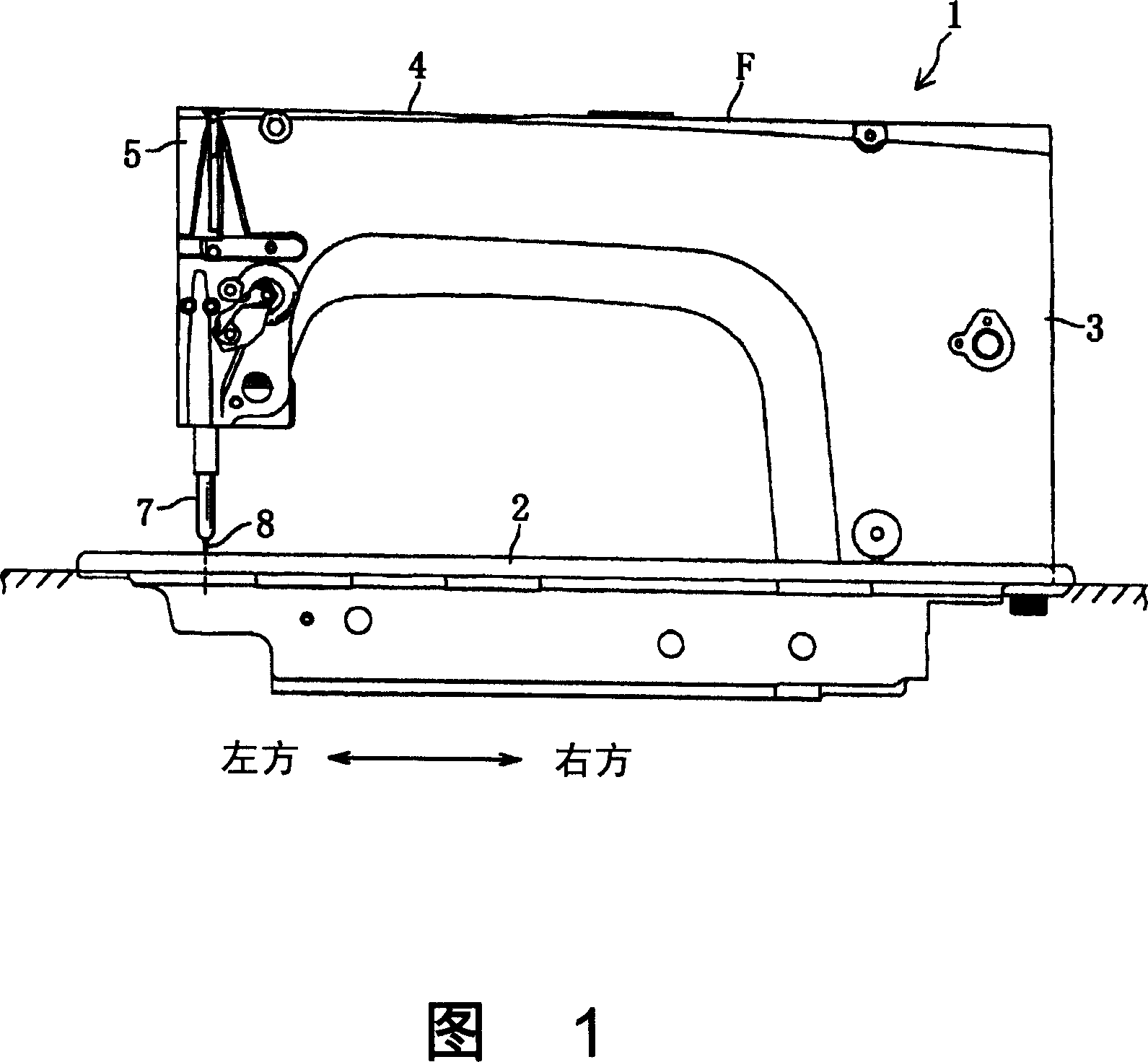
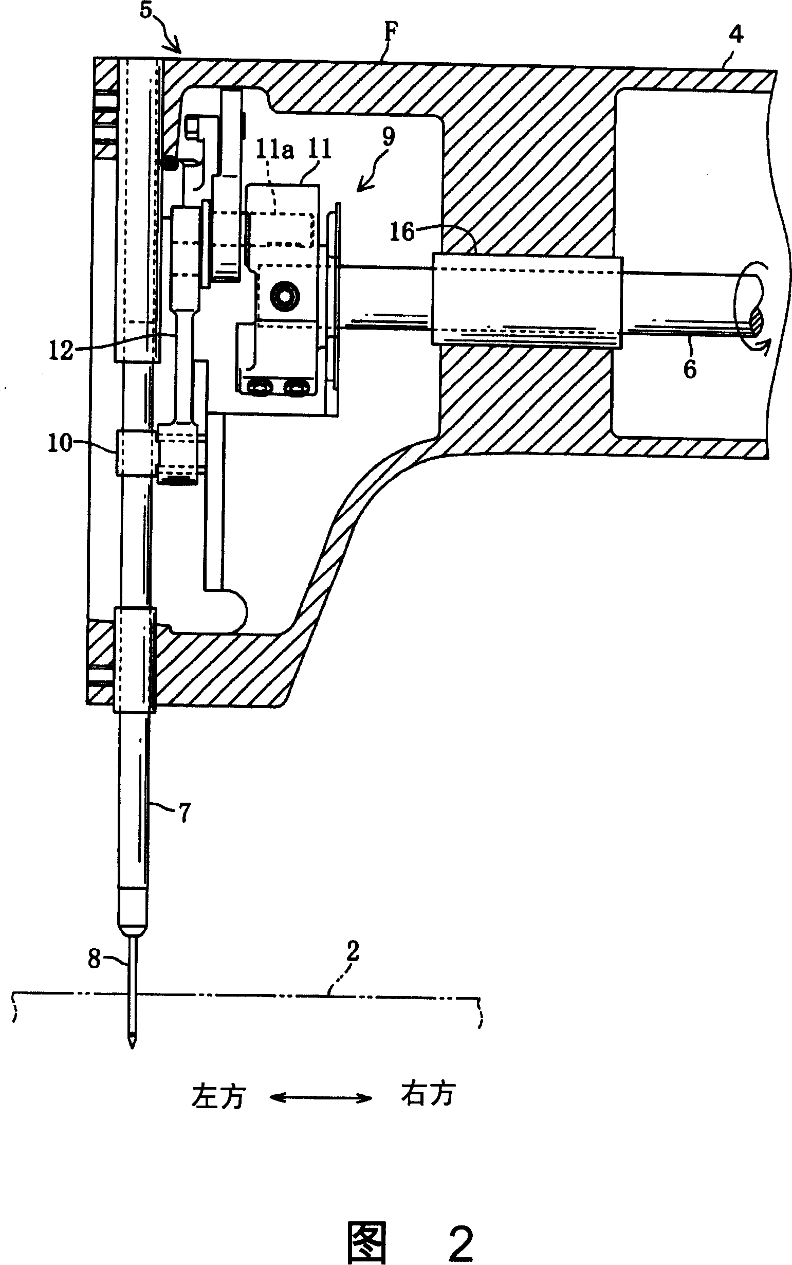
[0026] As shown in FIG. 1 , a sewing machine 1 includes a base plate 2 having a rotary hook, a column 3 erected on the right end of the base plate 2 , and a casing 4 extending leftward from the upper end of the column 3 . As shown in FIG. 2 , a main shaft 6 extending in the left-right direction is disposed inside the casing 4 . The lower part of the bottom plate 2 is equipped with: a lower shaft (not shown) that rotates synchronously with the main shaft 6; icon).

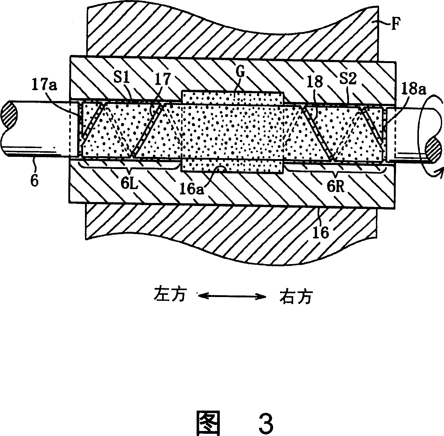
[0027] As shown in FIG. 2 , the main shaft 6 is rotatably supported by a cylindrical bearing member 16 fixed to a machine frame F of the sewing machine 1 . The left end of the main shaft 6 protrudes into the head 5 of the casing 4, and the protruding end is connected with a needle bar up and down movement mechanism 9 for making the needle bar 7 move up and down.

[0028] The needle...


PUM


Abstract

The present invention provides a bearing structure of a sewing machine. In the bearing structure in which a rotating shaft or a rotating member is rotatably supported by a bearing member or a supporting shaft fixed on a machine frame, the contact portion or The contact portion between the support shaft and the rotating member is formed with an annular grease receiving portion that holds grease for lubrication. On both sides of the grease receiving portion, there are formed a second grease holder that advances toward the grease receiving portion following the rotation of the rotating shaft or the rotating member. 1. The second helical groove, whereby the grease diffused between the rotating shaft and the bearing member or between the supporting shaft and the rotating member is returned to the grease housing under the action of the first and second helical grooves, preventing Grease leaks from both sides of the bearing member or rotating member, thereby preventing a decrease in lubricating performance due to insufficient grease, maintaining smooth rotation for a long period of time, and improving durability.

Description

technical field [0001] The present invention relates to a bearing structure for rotatably supporting a rotating shaft or a rotating member in a grease-lubricated manner through a bearing member or a supporting shaft fixed to a frame of a sewing machine. Background technique [0002] In a general mechanical drive system, when the rotating shaft rotating around the axis is rotatably supported by the bearing member, a lubricant is supplied between the rotating shaft and the bearing member to make the rotating shaft rotate smoothly, preventing the rotating shaft and the bearing member from Sintering (sticking). In industrial sewing machines and household sewing machines, in order to promote oil-free lubrication that does not use lubricating oil, the rotating shaft such as the high-speed rotating main shaft of the sewing machine is often supported by a bearing member with grease as a lubricant. [0003] For example, in the sewing machine described in Japanese Patent Application ...

Claims


Application Information

Patent Timeline
IPC IPC(8): D05B71/00F16N7/36
Inventor 和田哲也川岛义人柴田到桑原幸治
Owner BROTHER KOGYO KK
Why Eureka
Try Eureka