Compact spray cooling heat exchanger

A spray cooling and heat dissipation device technology, applied in the direction of cooling/ventilation/heating transformation, refrigerators, refrigeration components, etc., can solve the problems of increasing the size and cost of the heat dissipation system, high power supply, consumption, etc.

Inactive Publication Date: 2007-07-04
IND TECH RES INST
View PDF2 Cites 39 Cited by
  • Summary
  • Abstract
  • Description
  • Claims
  • Application Information

AI Technical Summary

Problems solved by technology

However, this technique uses a pump which increases the size and cost of the cooling system
In addition, in terms of the design of the atomizer, this technology proposes to use a structure similar to that of an inkjet head to generate micro-droplets after heating the fluid, but this design consumes a relatively high power supply
In addition, the spray circulation cooling device disclosed in U.S.

Method used


Image

  • Compact spray cooling heat exchanger
  • Compact spray cooling heat exchanger
  • Compact spray cooling heat exchanger

Examples


Embodiment Construction

[0044] In order to enable your examiner to have a further understanding of the features, purpose and functions of the present invention, the detailed structure and design ideas of the present invention will be described below so that the examiner can understand the characteristics of the present invention and describe in detail as follows:

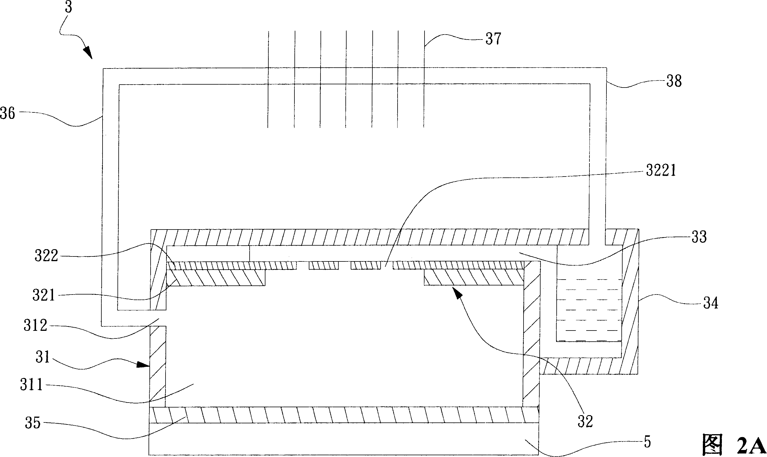
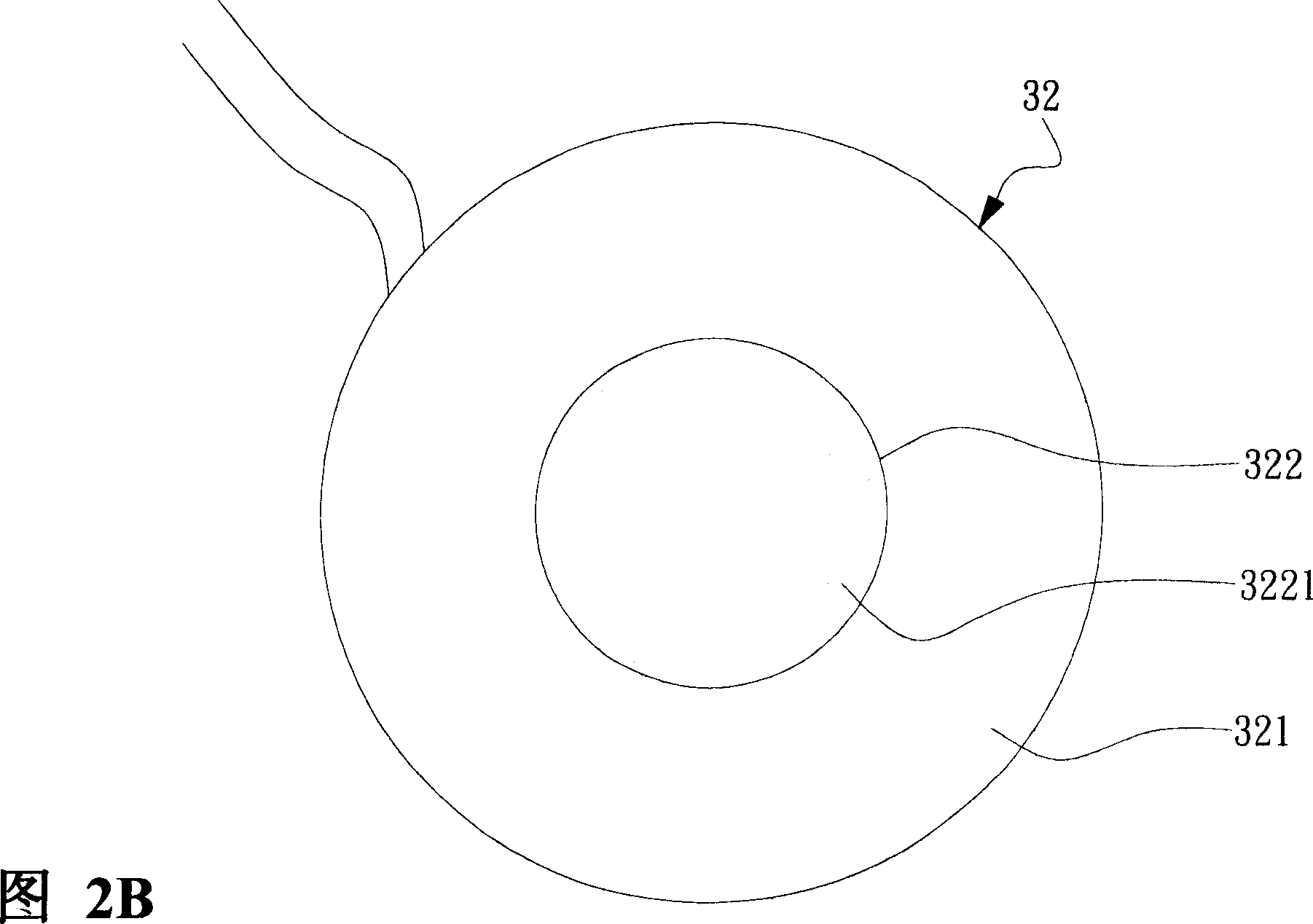
[0045] Please refer to FIG. 2A , which is a schematic view of the first preferred embodiment of the compact spray cooling heat dissipation device of the present invention. The spray cooling device 3 includes a spray cabin 31 , a liquid storage tank 34 , an atomizer 32 and a liquid delivery body 33 . The spray cabin 31 has a certain volume and is hollow inside to form a coolant spray space 311 . There is a heat-absorbing plate 35 made of a material with high thermal conductivity (such as copper or aluminum) at the bottom of the spray cabin 31; Please refer to FIG. 3 , which is a schematic diagram of a preferred embodiment of the heat abso...


PUM


Abstract

The invention relates to a compact atomization cooling radiator, which comprises liquid groove for storing cooling liquid; atomizing chamber connected to the thermal source; atomizer above the chamber which has piezoelectric plate and porous plate with several ejection holes; the atomizer can atomize the cooling liquid to generate atom in the atomizing chamber to take away thermal energy; and it also has one liquid transmitter for adsorbing the cooling liquid in the groove to the atomizer. The invention also can have condenser and transmission tube, to form a compact sealed atomization cooling radiator.

Description

technical field [0001] The invention relates to a heat dissipation device, in particular to a compact spray cooling heat dissipation device. Background technique [0002] The calorific value of electronic components increases rapidly with the improvement of semiconductor integration; how to improve the heat dissipation capacity of electronic components to ensure the normal operation of components has become a very important engineering topic. The direct air cooling technology currently widely used can no longer meet the heat dissipation requirements of electronic components with high heat flux, and other solutions must be sought. [0003] Among them, the spray cooling heat dissipation system uses the principle of phase change after the coolant absorbs heat to assist in heat dissipation. Due to the extremely high latent heat of liquid phase change, it is suitable for use in heat dissipation systems with high heat and high heat flux. At present, the spray cooling heat dissip...

Claims


Application Information

Patent Timeline
IPC IPC(8): H05K7/20F25B39/04H01L23/473
Inventor 熊治民王钦宏唐思维李炯毅
Owner IND TECH RES INST
Why Eureka
Try Eureka