Piston pump with improved efficiency

A piston pump, piston technology, applied in the direction of piston pumps, pumps, components of pumping devices for elastic fluids, etc., can solve problems such as noise, unfavorable flow characteristics, etc., achieve compact structure, short response time, and reduced number of parts Effect

Inactive Publication Date: 2007-07-04
ROBERT BOSCH GMBH
View PDF0 Cites 6 Cited by
  • Summary
  • Abstract
  • Description
  • Claims
  • Application Information

AI Technical Summary

Problems solved by technology

In addition, a spring for the return of the piston is arranged in the pressure chamber, which can lead to unfavorable flow characteristics in the pressure chamber and, in particular, problems caused by gas evolution compounded in the hydraulic fluid and noise problems

Method used


Image

  • Piston pump with improved efficiency
  • Piston pump with improved efficiency
  • Piston pump with improved efficiency

Examples


Embodiment Construction

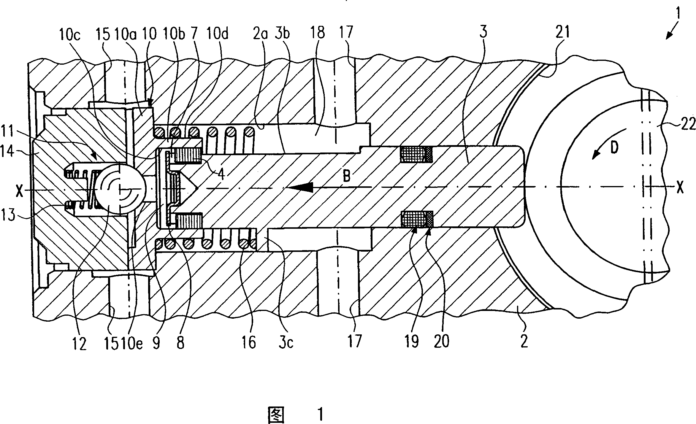
[0024] A piston pump 1 according to a first exemplary embodiment of the invention will be described below with reference to FIGS. 1 to 6 .

[0025] As shown in FIG. 1 , the piston pump 1 comprises a piston 3 which is arranged in a housing 2 . The housing 2 has a stepped hole 2 a for receiving the piston 3 . The piston 3 is driven by means of an eccentric 22 , the direction of rotation of which is indicated by the arrow D, which is arranged in the eccentric chamber 21 .

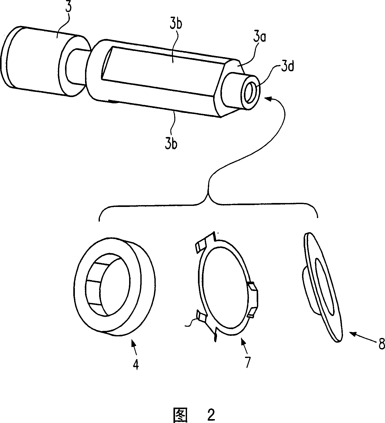
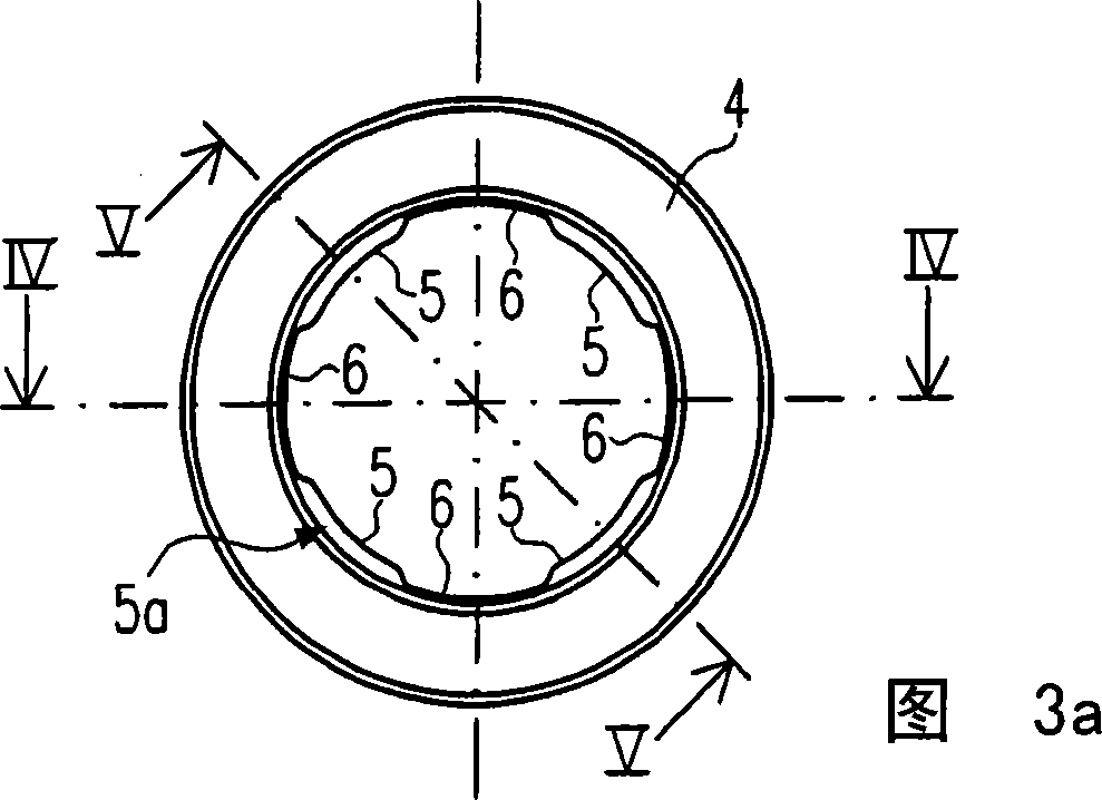
[0026] The piston 3 is shown in detail in the perspective view of FIG. 2 . It can be seen from FIG. 2 that the piston 3 has, at its end on the pressure chamber side, a stepped region 3 a and three flattened regions 3 b arranged along the circumference of the piston. It can be seen in particular from FIGS. 1 , 5 and 6 that a sealing element 4 is arranged on the stepped region 3 a. The sealing element 4 is fixed on the stepped region 3 a of the piston 3 by means of a spring element 7 and a plate-shaped holdin...


PUM


Abstract

The invention relates to a piston pump for the supply of hydraulic fluid, comprising a reciprocating piston (3), for generation of pressure in a pressure chamber (9), with a seal element (4) arranged on the piston (3), which seals the pressure chamber (9) against a low-pressure region (18) of the piton pump in the pressure phase and which opens a connection between the pressure chamber (9) and the low pressure region (18) in an inlet phase, in order to introduce hydraulic fluid into the pressure chamber.

Description

technical field [0001] The invention relates to a piston pump with improved efficiency for conveying hydraulic fluids, wherein the piston pump can be produced particularly cost-effectively. Background technique [0002] Different designs of piston pumps are known in the prior art. Radial piston pumps are usually used as piston pumps for vehicle brake systems, in which at least one piston can be moved back and forth by means of an eccentric. Piston pumps of this type are often used in electronic stability systems (ESP) or electrohydraulic brakes (EHB). Since such systems are increasingly used in smaller vehicles, the piston pumps should be very inexpensive to manufacture. A further requirement for such a piston pump is to make it as small as possible and to have as little weight as possible. Since future brake systems work with increasingly higher pressures, such piston pumps must additionally be able to deliver this desired pressure level. [0003] Such known piston pump...

Claims


Application Information

Patent Timeline
Patent Type & Authority Applications(China)
IPC IPC(8): F04B53/12F04B7/04F04B39/00
CPCF04B7/04F04B53/121F04B53/12F04B39/0016B60T8/4031F04B1/0408F04B49/22F05B2210/11Y10S417/00
Inventor R·谢普H·赫尔曼G·布洛施
Owner ROBERT BOSCH GMBH
Why Eureka
Try Eureka