Equipment group and procedure for storage of heat energy using electric current

A technology for storing thermal energy and equipment groups, which is applied in thermal storage equipment, lighting and heating equipment, household heating, etc., and can solve the problems of high heat storage capacity and long-term heat storage, which cannot be realized

Inactive Publication Date: 2007-07-11
伽博·苟德
View PDF3 Cites 2 Cited by
  • Summary
  • Abstract
  • Description
  • Claims
  • Application Information

AI Technical Summary

Problems solved by technology

[0031] The disadvantage of this type is that the melt generated from amorphous material is used for heat storage using heating i.e. dif

Method used


Image

  • Equipment group and procedure for storage of heat energy using electric current
  • Equipment group and procedure for storage of heat energy using electric current

Examples


Embodiment Construction

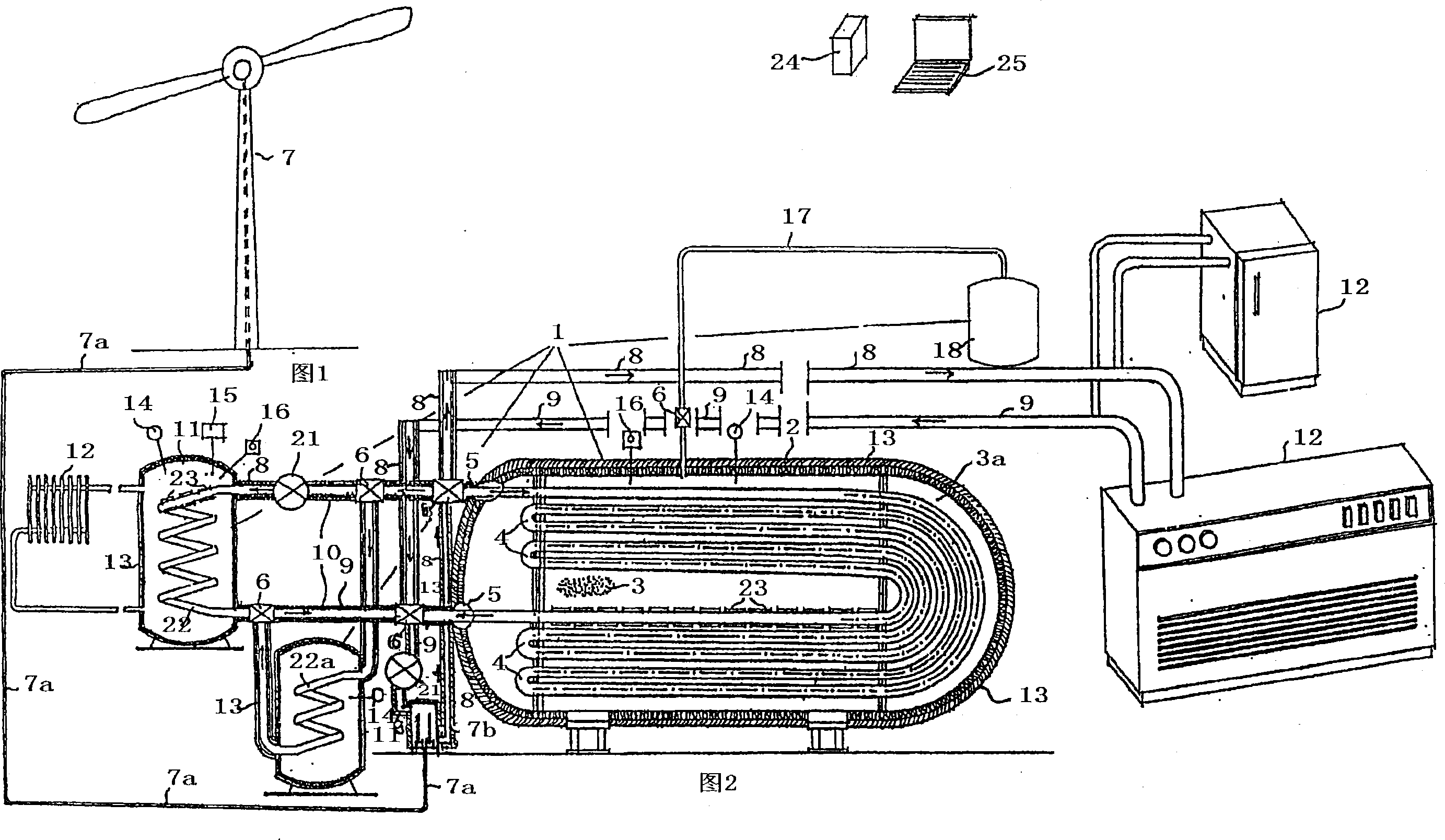
[0049] Figure 1 shows that the current from the subassembly 7 producing the current is led through the cable 7a to the heat generator 7b, from where the main pipe 8 conveying the heated heat transfer medium utilizes the circulation pump 21 and the valve 6 inserted in the inlet short pipe 5 And connected to the heating-cooling pipeline 4 of the heat storage tank 2, and return to the heat generator subassembly 7a through the valve 6 and the secondary pipeline 9 from the outlet short pipe 5 located at the end of the heating-cooling pipeline 4, thus forming a When the heat storage tank 2 is heated, it is filled with heat energy.

[0050] Figure 2 shows a heat storage tank 2 of a heat storage device 1 forming a basic unit, a heat exchanger 11 connected to the heat storage tank 2, a boiler 11a for generating hot water and an expansion tank 18 filled with an inert gas.

[0051] In FIG. 2 is shown a heat storage tank 2 of a heat storage device 1, which is filled with a crystalline hea...


PUM


Abstract

Equipment for storage of heat energy preferably for storage of heat energy by converting electric energy produced by plants utilizing wind energy into heat energy and using the stored heat energy for providing various heat supply services, and, in order to eliminate the disadvantages due to the intermittent operation of plants utilizing wind energy, using the stored heat energy for generating electric energy during windless period; furthermore, storing the energy by means of cheap electric energy produced by the power stations during night and using it during peak load periods.

Description

technical field [0001] The invention relates to a set of devices and a process for storing thermal energy using electric current Background technique [0002] Energy reserves are limited in the world; their extraction is becoming increasingly expensive. In particular, the predicted severe shortage of petroleum reserves in the middle of this century will cause severe problems and energy shortages; in fact, the problem of using petroleum derivatives that are mostly burned as a substitute has not yet been solved. At the same time, since fossil fuels are burned, the pollutants sent into the environment cause serious environmental pollution and increase the carbon dioxide content in the atmosphere, thus aggravating the "greenhouse" effect with its serious consequences. Sulfur dioxide sent into the atmosphere leads to acid rain which causes significant damage to the biosphere. [0003] In order to solve these problems which are becoming more and more serious both for the present...

Claims


Application Information

Patent Timeline
IPC IPC(8): F24D11/00F24J2/14F28D20/02F24S23/74
CPCY02B10/20F28D20/028F24D2200/15Y02E60/145F24D11/002Y02E60/14
Inventor 伽博·苟德
Owner 伽博·苟德
Why Eureka
Try Eureka