
Machine for fitting and removing a tyre and method for operating the machine

a technology for removing tyres and machines, which is applied in vehicle tyre testing, instruments, transportation and packaging, etc., can solve the problems of uneven tread, wheel unbalance, and additional unbalance, and achieve the effect of fast and effective manner and ample space for operation

Active Publication Date: 2018-06-19
NEXION SPA
View PDF20 Cites 14 Cited by
  • Summary
  • Abstract
  • Description
  • Claims
  • Application Information

AI Technical Summary

Benefits of technology

This patent describes a machine that changes tires, which has a roller that allows the tire repair specialist to work around the wheel with ease. The roller helps the specialist quickly switch between different tools, like the roller and a removal tool. The result is faster and more efficient tire changes.

Problems solved by technology

This is due basically to machining defects, non-homogeneity of construction materials, and the existence of inflation valves which, although relatively light in weight, constitute additional unbalanced weights.
Further causes of the wheel unbalance are linked, for example, to deformation of the rims (caused by impacts and deep potholes), out of roundness of the tyre after a certain mileage, flattening of the tread during sharp braking, and errors during fitting and removal of the wheel.
These unbalances generate forces which cause annoying vibrations at the steering wheel, chassis and frame of the vehicle, in particular at high speeds.
The asymmetries and non-uniformity of the rim / tyre assembly cause variations to the radial, lateral and tangential force during rotation of the wheel subjected to a load.
In effect, even if the vehicle wheel is balanced by counterweights, some non-uniformity in the tyre structure may give rise to lateral forces when the wheel is set in rotation under the action of a load
One issue concerns the fixing or locking of the wheel on the rotary wheel-holder unit, in particular in the case of tyre changer machines.
The locking system used in the tyre changer machines is robust, but it is a relatively imprecise.
This limits the accuracy of the measurements performed with the roller, thus adversely affecting the reliability.
Another issue concerns the overall dimensions, as the roller tends be bulky.
That issue is particularly felt in the case of tyre changer machines equipped with a roller, as the tyre changer machines are equipped with numerous tools, which must be used by the tyre repair specialist on the wheel, simultaneously with or at different stages of the use of the tyre changer machine (for example, bead breakers, removal, fitting).
In actual fact, this solution constitutes only a temporary remedy which often proves unsatisfactory because the amplitude of the vibrations produced remains high.
Further, removing parts of the tyre from the tread means reducing the thickness of the tread and, consequently, shortening the working life of the tyre.
Among the causes of lateral forces connected with non-uniformity of tyre structure are defects known as conicity and ply steer.
Conicity is generally associated with non-uniformity in the tyre structure such that one side wall is more rigid than the other.
These forces are generated by non-uniformity in the distribution of the outer ply layers of the of the tyre.
To verify these standards, it is therefore necessary to set the wheel in rotation at a relatively high speed which wheel service machines, especially tyre changer machines, are not capable of reaching.
Another issue relates in general to all the wheel service machines equipped with a roller, and it relates to the completeness and the actual utility for diagnostic purposes of the data provided to the machine thanks to the measurements of the roller.
However, these measurements do not allow defects to be distinguished which are linked to the conicity, or, more generally, the elastic response of the wheel, from defects which are linked to the structure of the tyre (due, for example, by possible damage).
Moreover, these measurements do not provide diagnostic information on the noise level of the tyre.

Method used


Image

  • Machine for fitting and removing a tyre and method for operating the machine
  • Machine for fitting and removing a tyre and method for operating the machine
  • Machine for fitting and removing a tyre and method for operating the machine

Examples


Embodiment Construction

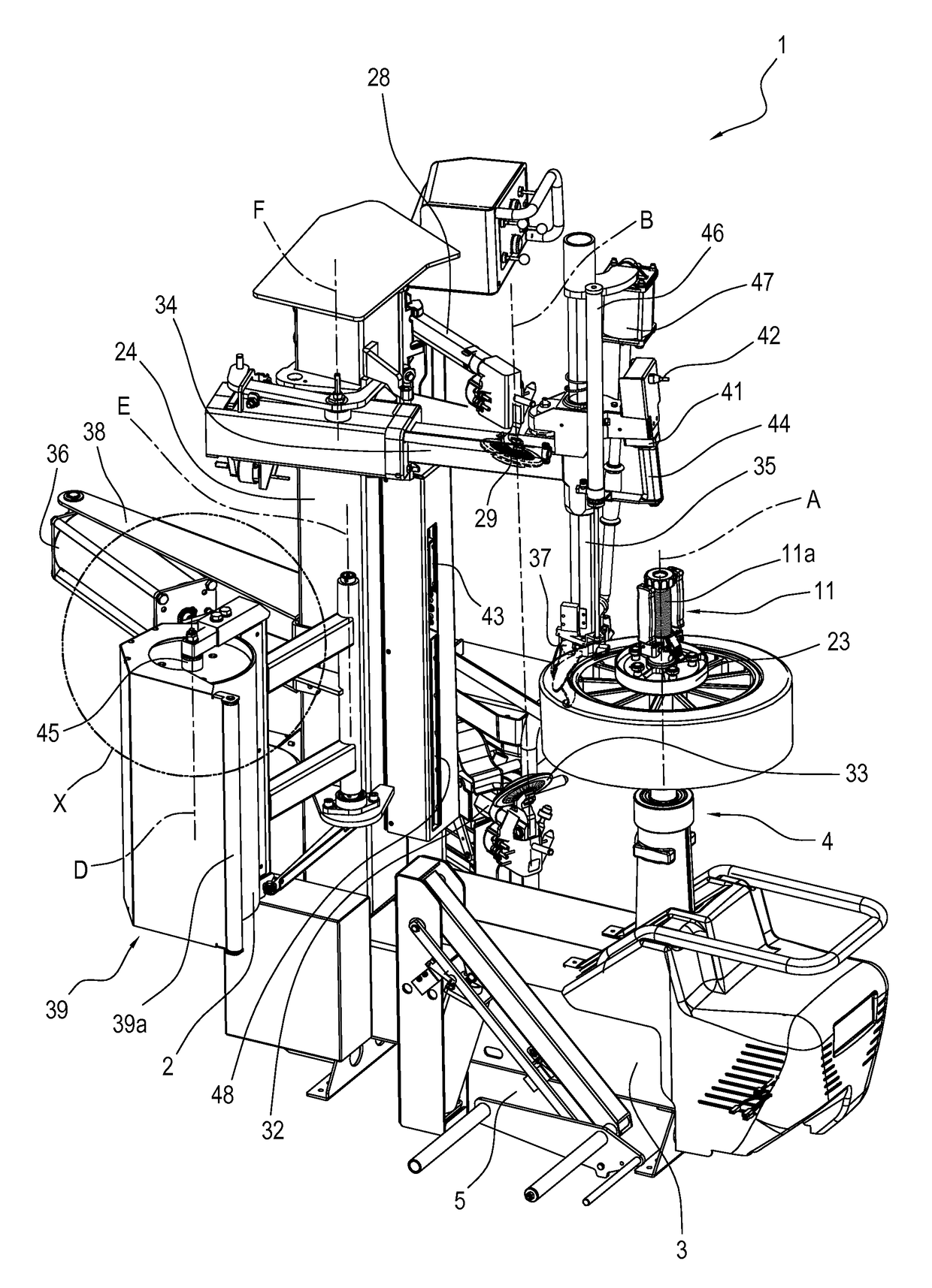
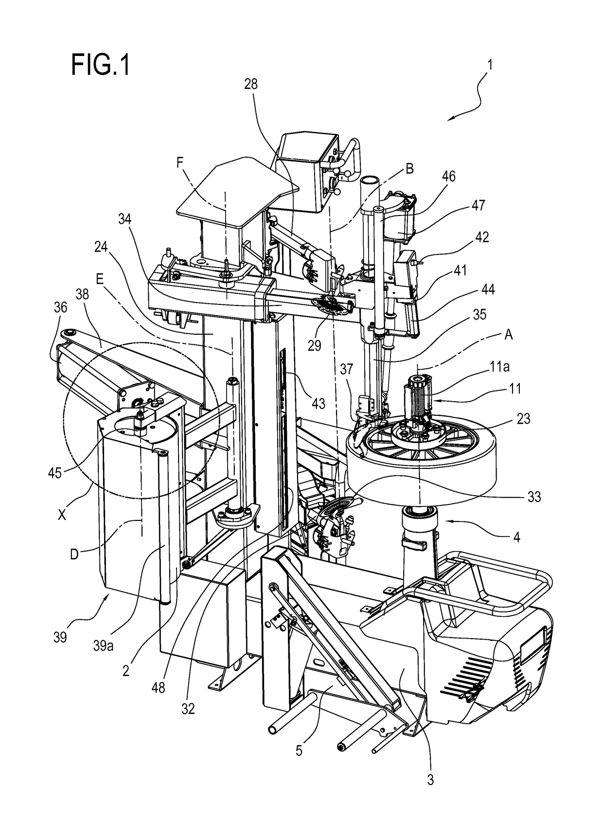
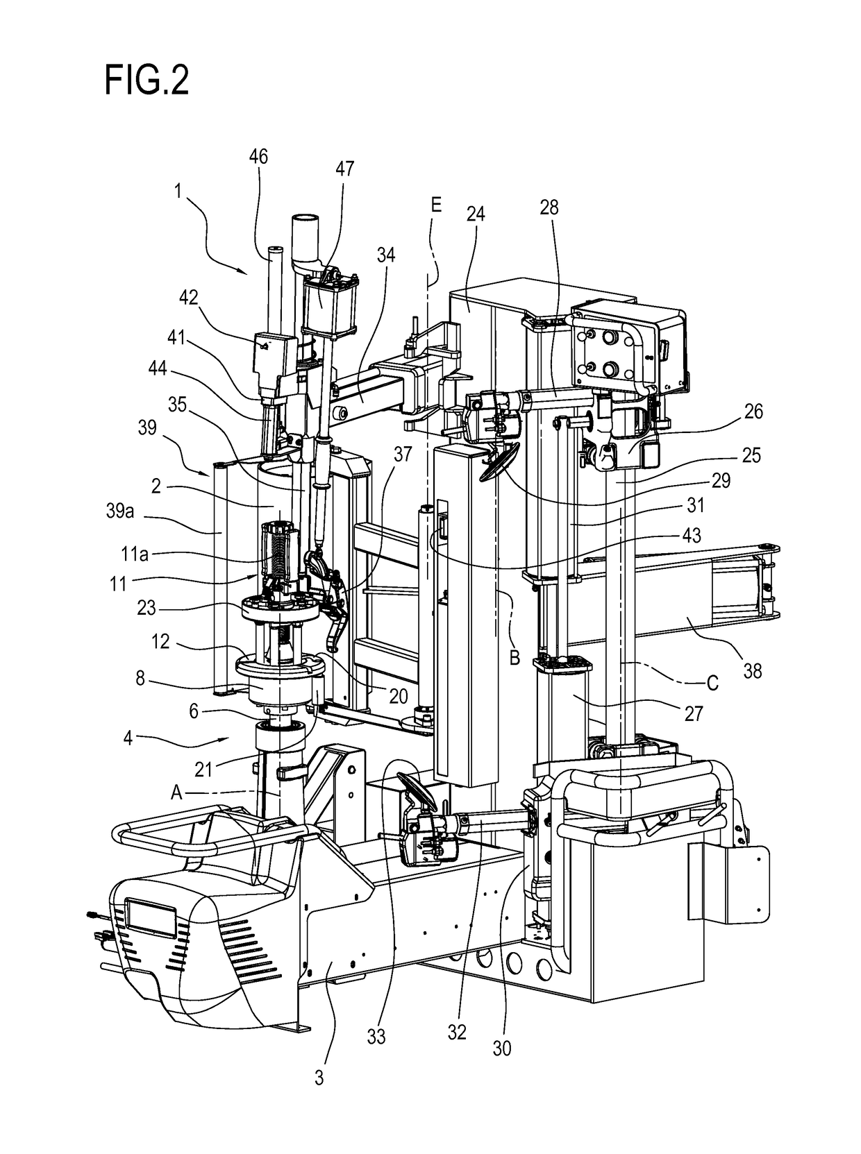
[0148]With reference to the accompanying drawings, the numeral 1 denotes a wheel service machine. More specifically, in the embodiment illustrated, the numeral 1 denotes a machine for fitting and removing a tyre to / from a corresponding vehicle wheel rim (that is, a tyre changer) comprising a load roller 2, according to this description.

[0149]The machine 1 comprises a frame. Preferably, the frame comprises a base 3. The base 3 comprises a wheel-holder unit 4. The wheel-holder unit 4 is designed to fix the wheel by means of a locking device and to rotate it about an axis of rotation A. Preferably, the first axis of rotation A is vertical.

[0150]Preferably, the base 3 comprises a mechanism 5 for lifting the wheel, of known type.

[0151]The wheel-holder unit 4 comprises a supporting shaft 6 having a first and a second end. The first end of the supporting shaft 6 is connected to rotation means 7. The second end of the supporting shaft 6 is configured for coupling to a supporting apparatus 8...


PUM


Abstract

Described is a machine (1) for fitting and removing a tire from a corresponding wheel rim of a vehicle, comprising: a wheel-holder unit (4), which rotates about a first axis (A); at least one bead breaker tool (29), movable along a second axis (B) parallel to the first axis (A); a roller (2) rotating about a fourth axis (D) parallel to the first axis (A) and configured to move by rotation about a fifth axis (E) spaced from the fourth axis (D), between an active position where it is in contact with a tire tread of the wheel mounted on the wheel-holder unit (4), to a position of non-interference relative to the tire; at least one sensor (40) connected to the roller (2) for detecting a signal representing a force transmitted to the roller (2) by the tire; a removal tool (37), which is movable by rotation about a sixth axis (F) parallel to the first axis (A) and spaced from it, between a first position proximal to the first axis (A) and a second position distal from the first axis (A), which is movable in a direction parallel to the first axis (A) and movable towards and away from the sixth axis (F).

Description

FIELD OF THE INVENTION[0001]This invention relates to a machine for fitting and removing a tyre and method for operating the machine.[0002]The invention applies to the field of equipment for tyre repair specialists and in particular to that of the wheel service machines.BACKGROUND OF THE INVENTION[0003]It should be noted that the term wheel (for vehicle) means the coupling between a tyre and a corresponding rim (that is, the overall tyre / rim). Wheel service machines are divided into two main types:[0004]balancing machines, configured to measure the static and / or dynamic unbalancing of a wheel;[0005]machines for fitting and removing a tyre on a corresponding rim (also known in the prior art as a “tyre changer machine”).[0006]The balancing of a wheel for a vehicle is performed by the tyre repair specialist in order to eliminate or reduce to a minimum the effects of the asymmetric distribution of the weights of the tyre / rim assembly. These asymmetries are usually compensated for by the...

Claims


Application Information

Patent Timeline
Patent Type & Authority Patents(United States)
IPC IPC(8): B60C25/138G01M1/06G01M17/02B60C25/05
CPCB60C25/138B60C25/056B60C25/0542G01M1/06G01M17/022B60C25/0521B60C25/0548
Inventor CORGHI, GIULIO
Owner NEXION SPA
Learn More