
Multiple contact circuit breaker

a circuit breaker and contact technology, applied in the field of circuit breakers, can solve the problems of safety hazards, gap widening between contacts, breaker will trip, etc., and achieve the effect of more effective and rapid operation

Active Publication Date: 2018-06-19
CARLING TECH
View PDF10 Cites 2 Cited by
  • Summary
  • Abstract
  • Description
  • Claims
  • Application Information

AI Technical Summary

Benefits of technology

The present invention provides a circuit interrupter with a structure designed to function more effectively and quickly, and to extinguish any arc that may develop in the gap between the contacts. The invention also provides a system and method to minimize the arcing that occurs in a DC system when the contacts are opened or closed. By including a series set of contacts, this doubles the distance of one set of contacts, thereby increasing the arc voltage for breaking the arc more effectively and quickly.

Problems solved by technology

If a fault condition such as a power surge occurs in the electrical wiring, the breaker will trip.
A problem with circuit interrupters that operate by separating contacts arises because the energized contacts separate when the circuit breaker is tripped, causing a gap to widen between the contacts while the movable contact moves from the closed position to the open position.
The creation of an arc during switching or tripping the circuit interrupter can result in undesirable side effects which can negatively affect the operation of the circuit interrupter, and which can create a safety hazard.
These effects can have consequences for the operation of the circuit interrupter.
One possible consequence is that the arc may short to other objects in the circuit interrupter and / or to surrounding objects, causing damage and presenting a potential fire or electrocution safety hazard.
Another consequence of arcing is that the arc energy damages the contacts, causing some material to escape into the air as fine particulate matter.
The debris which has been melted off of the contacts can migrate or be flung into the mechanism of the circuit interrupter, destroying the mechanism or reducing its operational lifespan.
However, generating an electromagnetic field to move the arc consumes power, and generates heat in the device.
Arc quenching devices can be effective in protecting devices, however, they do have lifespans that limit their effectiveness over time.
Additionally, elaborate arc quenching systems can add significant cost to the circuit breaker.
However, this method is not available for use in DC systems as there is no zero crossing.

Method used


Image

  • Multiple contact circuit breaker
  • Multiple contact circuit breaker
  • Multiple contact circuit breaker

Examples


Embodiment Construction

[0041]Referring now to the drawings, wherein like reference numerals designate corresponding structure throughout the views.

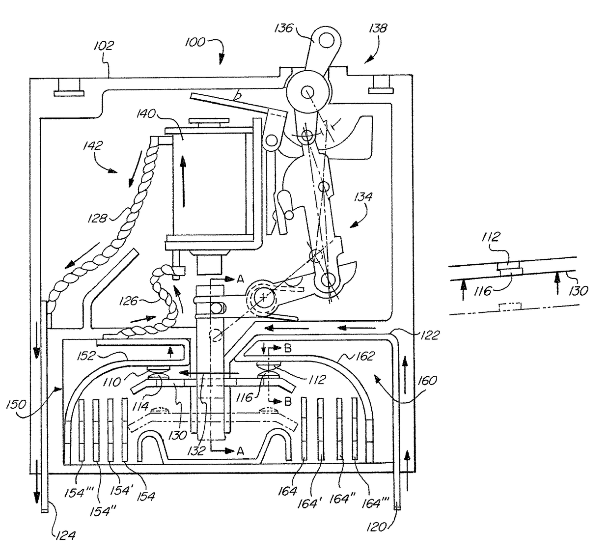
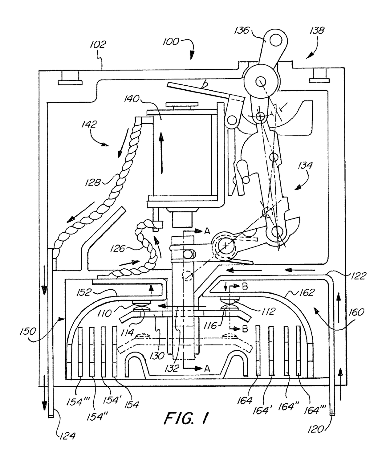
[0042]FIG. 1 illustrates components of an example circuit interrupter 100 having multiple contacts according to aspects of the invention.

[0043]Circuit interrupter 100 may be any device which can be used to make and break a circuit using contacts. For example, it will be clear to those having ordinary skill in the art that circuit interrupter 100 may be a simple switch, or may be implemented as a circuit breaker having a housing 102, for example. Housing 102 may include vents to allow gasses and debris produced by arcing to escape housing 102.

[0044]Circuit interrupter 100 includes a second stationary contact 112, both of that is electrically connected to line terminal 120 through conductor 122. First stationary contact 110 is electrically connected to load terminal 124 through conductor 126, overcurrent measurement device 140 and conductor 128.

[0045]The line ter...


PUM


Abstract

A circuit interrupter having at least two sets of contacts that are electrically connected in series such that when the at least two sets of contacts are opened, they are opened simultaneously. This functions to increase the distance between the sets of contacts as the distance is additive for the series connected sets of contacts, which increases the arc voltage for breaking any arc that may form between the individual sets of contacts more effectively.

Description

FIELD OF THE INVENTION[0001]The invention relates to the field of circuit breakers. More specifically, the invention relates to a circuit breaker that includes at least two series connected contacts that are simultaneously opened so as to increase the arc voltage upon contact opening.BACKGROUND OF THE INVENTION[0002]Circuit interrupters are electrical components that can be used to break an electrical circuit, interrupting the current flow. A basic example of a circuit interrupter is a switch, which generally consists of two electrical contacts in one of two states; either closed, meaning that the contacts are touching and electricity can flow between them, or open, meaning that the contacts are separated, and no electricity can flow between them. A switch may be directly manipulated by a human to provide a control signal to a system, such as a computer keyboard button, or to control power flow in a circuit, such as a light switch.[0003]Another example of a circuit interrupter is a ...

Claims


Application Information

Patent Timeline
IPC IPC(8): H01H33/08H01H1/36
CPCH01H1/36H01H33/08H01H2205/002H01H2201/004H01H73/04H01H73/18H01H1/2083H01H71/2409H01H89/08
Inventor FASANO, MICHAEL
Owner CARLING TECH
Learn More