Controller for internal combustion engine and method for controlling internal combustion engine

a technology for internal combustion engines and control circuits, applied in the direction of electric control, fuel injection control, machines/engines, etc., can solve the problem that the drive circuit of the in-cylinder injection valve may require a large thermal rating

Active Publication Date: 2018-07-03
TOYOTA JIDOSHA KK
View PDF2 Cites 0 Cited by
  • Summary
  • Abstract
  • Description
  • Claims
  • Application Information

AI Technical Summary

Benefits of technology

[0005]It is an object of the present invention provide a controller for an internal combustion engine that limits situations in which the peak value of the current flowing through the coil becomes excessively nigh while enabling the injection of fuel from the in-cylinder injection valves.

Problems solved by technology

As a result, a drive circuit of the in-cylinder injection valves may require a large thermal rating.

Method used


Image

  • Controller for internal combustion engine and method for controlling internal combustion engine
  • Controller for internal combustion engine and method for controlling internal combustion engine
  • Controller for internal combustion engine and method for controlling internal combustion engine

Examples


first embodiment

[0036]A first embodiment of a controller for an internal combustion engine will now be described with reference to the drawings.

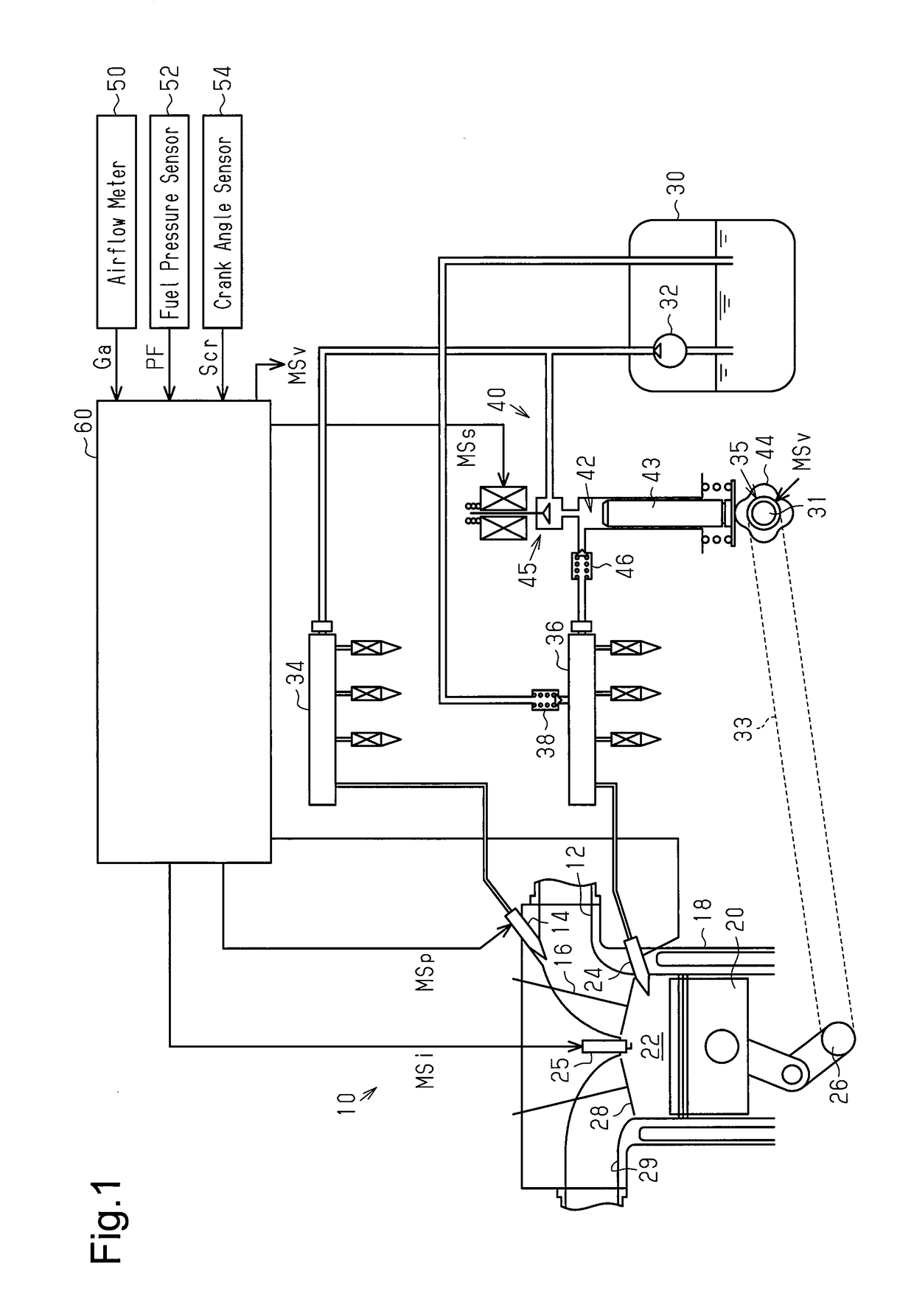
[0037]As shown in FIG. 1, an internal combustion engine 10 includes an intake passage 12. A port injection valve 14 is arranged in the intake passage 12. An intake valve 16 opens and draws fluid from the intake passage 12 into a combustion chamber 22 defined by a cylinder 18 and a piston 20. An in-cylinder injection valve 24 and an ignition 25 projects into the combustion chamber 22. A mixture of air and fuel is ignited by an ignition 25 and burned in the combustion chamber 22. The piston 20 converts the combustion energy of the air-fuel mixture in the combustion chamber 22 into rotational energy of a crankshaft 26. An exhaust valve 28 opens to discharge the burned air-fuel mixture as exhaust gas to an exhaust passage 29.

[0038]A fuel tank 30 contains the fuel injected from the port injection valve 14 and the in-cylinder injection valve 24. A feed pump 32 su...

second embodiment

[0091]A second embodiment of a controller for an internal combustion engine will now be described with reference to the drawings.

[0092]In the first embodiment, when the discharge amount of the high-pressure fuel pump 40 is not operated to a value that is greater than zero to control the fuel pressure PF, conditions (C) and (D) are not satisfied. Thus, it is determined that the control of fuel pressure control processor M20 has not converged. In the second embodiment, instead of using conditions (C) and (D) to determine convergence, condition (E) is used. Condition (E) indicates that the fuel pressure control processor M20 has performed feedback control of the fuel pressure PF to the target fuel pressure PF* to discharge fuel from the high-pressure fuel pump 40.

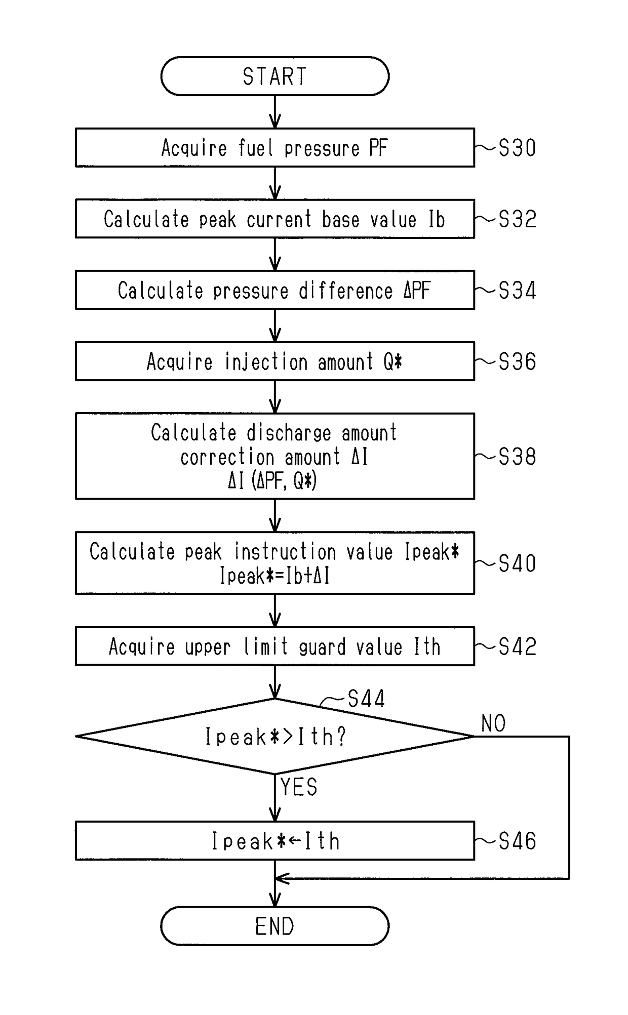
[0093]FIG. 10 shows the procedures for setting the upper limit guard value Ith in the second embodiment. In the processing shown in FIG. 10, the CPU 92 executes programs stored in the memory 94 to realize the processing of the...


PUM


Abstract

A controller for an internal combustion engine including a fuel pressure control processor that controls a fuel pressure at a target fuel pressure, an instruction value calculating processor that calculates a peak instruction value, an upper limit guard processor that executes a guard process on the peak instruction value, an energizing processor that energizes the coil based on the peak instruction value that has undergone the guard process, a convergence determination processor that determines whether or not the detected fuel pressure has converged on the target fuel pressure, and a decreasing processor that decreases the upper limit guard value to a lower value when the fuel pressure has converged on the target fuel pressure than when the fuel pressure has not converged on the target fuel pressure.

Description

BACKGROUND ART[0001]The present invention relates to a controller for an internal combustion engine.[0002]An internal Combustion engine includes in-cylinder injection valves, a supply passage, and a high-pressure fuel pump. Each in-cylinder injection valve includes a coil that opens the valve when energized to inject fuel into a corresponding combustion chamber of the internal combustion engine, The supply passage supplies fuel to the in-cylinder injection valves. The high-pressure fuel pump supplies pressurized fuel to the supply passage. Japanese Laid-Open Patent Publication No. 2014-238047 describes a device that applies a valve-opening voltage to a coil incorporated in an in-cylinder injection valve in order to increase the current flowing to the coil. Then, a holding voltage, which is smaller than the valve-opening voltage, is intermittently applied to the coil so that the current flowing to the coil has a holding current value. In particular, the device switches from the valve...

Claims


Application Information

Patent Timeline
Patent Type & Authority Patents(United States)
IPC IPC(8): F02D41/38F02D41/20
CPCF02D41/3863F02D41/20F02D41/3836F02D41/3845F02D2200/0604F02D2041/2048F02D2041/389F02D2200/0602F02D41/38
Inventor NAKANO, TOMOHIRO
Owner TOYOTA JIDOSHA KK
Why Eureka
Try Eureka