Mass analyzing electromagnet and ion beam irradiation apparatus

Inactive Publication Date: 2016-05-05
NISSIN ION EQUIP CO LTD
View PDF1 Cites 0 Cited by
  • Summary
  • Abstract
  • Description
  • Claims
  • Application Information

AI Technical Summary

Benefits of technology

The patent proposes a technique to prevent deposits from accumulating on the inner wall of an analysis tube when an ion beam collides with the tube's interior. This technique helps to improve the accuracy of the analysis.

Problems solved by technology

Then, during operation of the apparatus, unnecessary ion components and neutral particles in an ion beam can collide with the deposit, thereby causing peeling of the deposit from the inner wall surface of the analysis tube.
In this case, the peeled deposit is ejected toward a target (a substrate such as a silicon wafer or a glass substrate) and mixed in the target, resulting in contamination of the target.
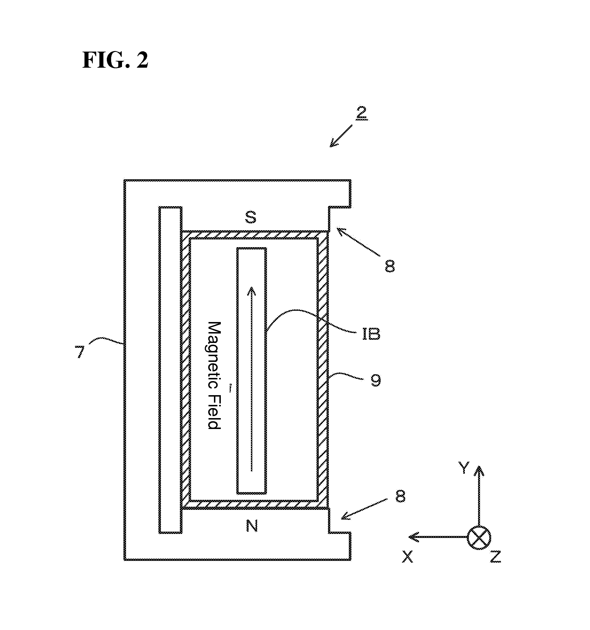
If the spatial zone inside the analysis tube is excessively enlarged, a distance between the magnetic poles disposed outside the analysis tube is increased, and thereby a magnetic field distribution within the analysis tube becomes non-uniform.
The non-uniform magnetic field distribution is likely to cause a situation where a shape of an ion beam is changed during deflection of the ion beam, causing a negative influence on mass analysis on the ion beam.
This leads to a concern that such chemical components will be accumulated over time, and the resulting deposit can be peeled from the inner wall surface due to a collision with a peripheral end of an ion beam at a certain timing, etc., and ejected toward a target, resulting in contamination of the target.
For example, in the case where ion implantation is performed using different types of ions, if previously used ions are peeled from the inner wall surface of the analysis tube during ion implantation subsequently performed using different ions, and mixed in a target, the target is undesirably contaminated.
Moreover, it is difficult to exactly reproduce an ideal design shape of an ion beam by controlling respective applied voltage to electrodes constituting an extraction electrode system of an ion source.
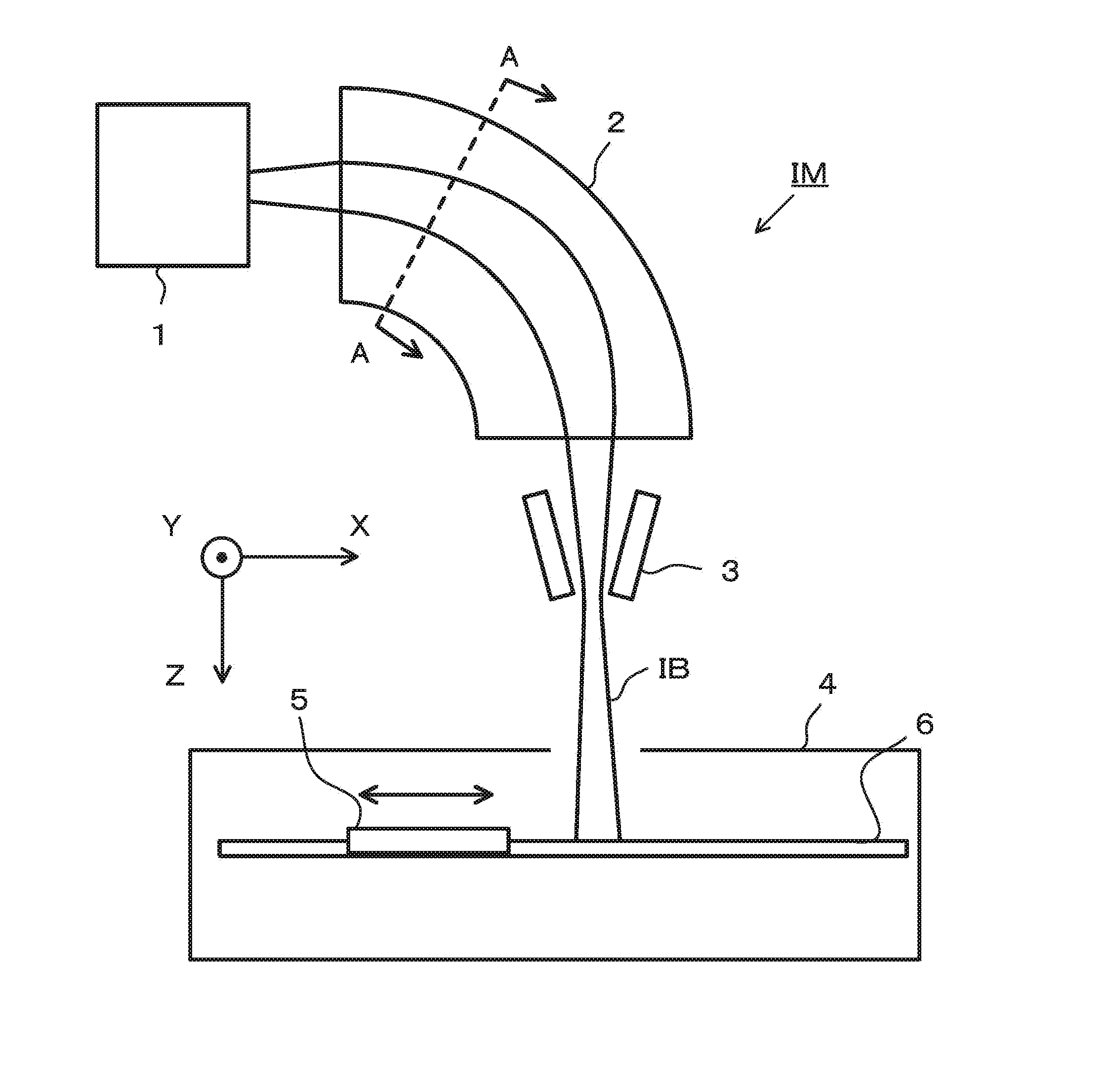
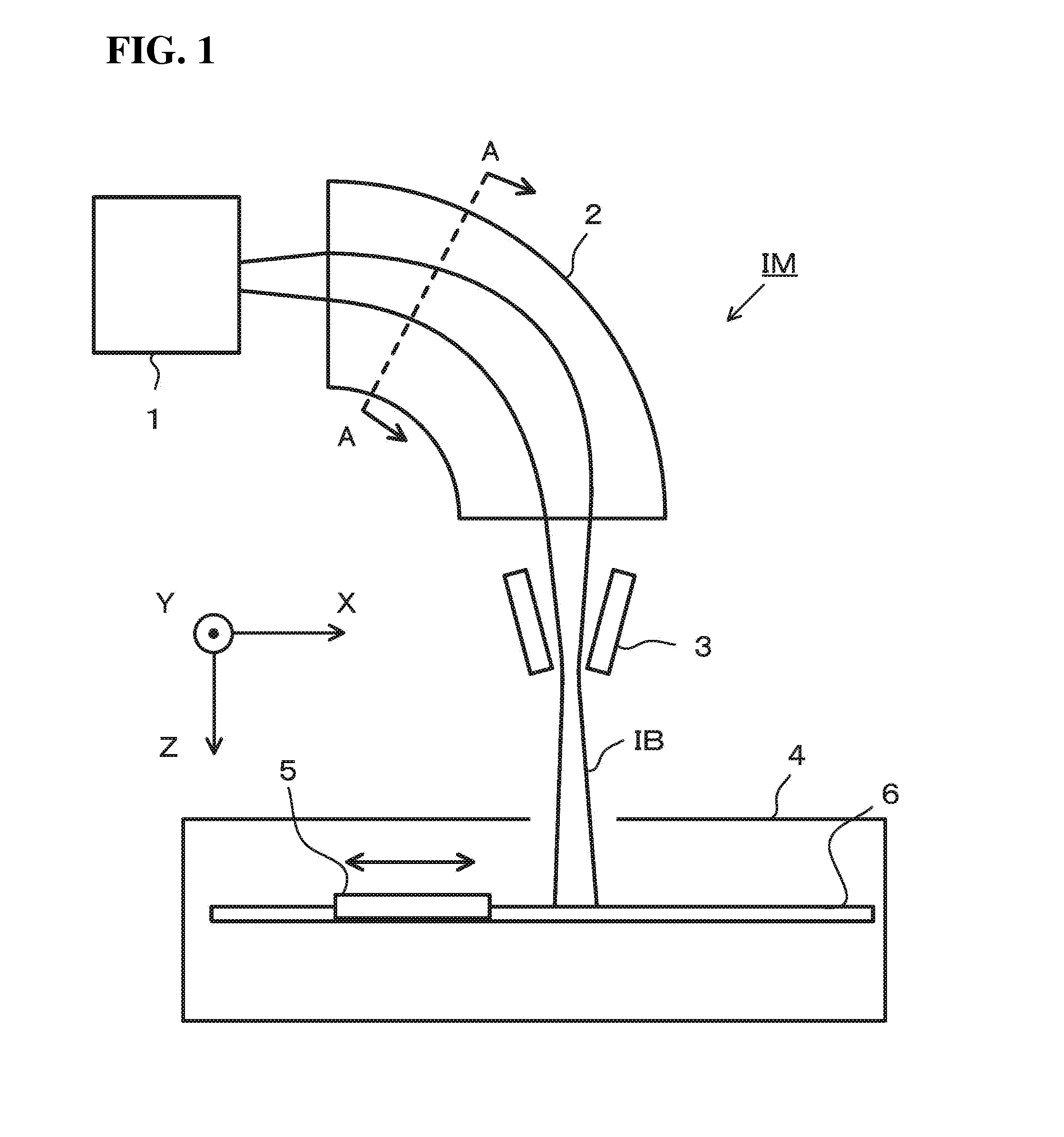
Thus, due to an influence of such a diverged component, when an ion beam passes through the analysis tube of the mass analyzing electromagnet, a peripheral end of the ion beam undesirably collides with the inner wall surface of the analysis tube.
As a result, the same problem as that in the aforementioned divergence caused by the space-charge effect occurs.
On the other hand, in a region far away therefrom, it is impossible to really expect such an effect.
Moreover, due to divergence of the ion beam caused by the space-charge effect and the extraction electrode system, a deposit also occurs in a heretofore-unanticipated region of the inner wall surface of the analysis tube.
For example, if there is a problem with a diverged component of the ion beam on an upper side of the ion beam, the same problem is highly likely to occur on a lower side of the ion beam.
On the other hand, in a region far away therefrom, it is impossible to really expect such an effect.
Moreover, due to divergence of the ion beam caused by the space-charge effect and the extraction electrode system, a deposit also occurs in a heretofore-unanticipated region of the inner wall surface of the analysis tube.

Method used


Image

  • Mass analyzing electromagnet and ion beam irradiation apparatus
  • Mass analyzing electromagnet and ion beam irradiation apparatus
  • Mass analyzing electromagnet and ion beam irradiation apparatus

Examples


Embodiment Construction

[0044]With reference to the drawings, the present inventive concept will now be described based on an exemplary embodiment thereof.

[0045]FIG. 1 is a schematic diagram illustrating a configuration of an ion beam irradiation apparatus IM according to an exemplary embodiment. An ion beam IB illustrated in FIG. 1 is a ribbon beam having an approximately rectangular shape in its cross-section taken along a plane perpendicular to a traveling direction of the ion beam IB (ion beam traveling direction), wherein a dimension of the ion beam IB in a direction of a long side of the approximately rectangular-shaped cross-section is greater than a dimension of an aftermentioned target 5 in the same direction. The ion beam IB in an exemplary embodiment and any other exemplary embodiment has a positive electrical charge.

[0046]The illustrated X-, Y- and Z-directions relate to the ion beam IB just after it enters a processing chamber 4. Specifically, the X-direction is a direction of a short side of ...


PUM


Abstract

A mass analyzing electromagnet is provided. The mass analyzing electromagnet includes an analysis tube having an internal zone formed as a passage for the ion beam; anda shield member mounted to an inner wall surface of the analyzing tube, a portion of the shield member intersecting with a direction perpendicular to a traveling direction of an ion beam and a mass-based separation direction of the ion beam so as to block a portion of the ion beam.

Description

BACKGROUND[0001]1. Field[0002]The present disclosure relates to an ion beam irradiation apparatus, and a mass analyzing electromagnet comprising an analysis tube and usable in the ion beam irradiation apparatus.[0003]2. Description of the Related Art[0004]As an apparatus for performing substrate processing in vacuum by using an ion beam, there has been known an ion beam irradiation apparatus such as an ion implantation apparatus or an ion doping apparatus. Specifically, an apparatus disclosed in JP2536837B has been employed.[0005]The apparatus disclosed in JP2536837B is an ion implantation apparatus in which an ion beam flight tube (also called “analysis tube”) is provided in a sandwiched manner between magnetic poles of a mass analyzing electromagnet. JP2536837B points out as a problem the following phenomenon occurring within the analysis tube.[0006]Unnecessary ion components and neutral particles separated from an ion beam through mass analysis in the mass analyzing electromagnet...

Claims


Application Information

Patent Timeline
IPC IPC(8): H01J49/30H01J37/317H01J37/147H01J49/20
CPCH01J49/30H01J49/20H01J2237/31701H01J37/1472H01J37/3171H01J37/05H01J2237/055
Inventor TATEMICHI, JUNICHIDOHI, SHOJIRONISHIMURA, IPPEI
Owner NISSIN ION EQUIP CO LTD
Why Eureka
Try Eureka