In-situ testing equipment for testing micromechanical properties of material in multi-load and multi-physical field coupled condition

a micromechanical and insitu testing technology, applied in the direction of material strength using steady bending force, material strength using steady torsional force, etc., can solve the problem that the inner mechanism of microstructural changes and macromechanical properties of a material cannot be effectively combined to characterize the performance of the material, and the mechanical property test in a single load manner cannot accurately reflect the load applied to the material and component in an actual situation

Active Publication Date: 2018-07-03
JILIN UNIV
View PDF17 Cites 10 Cited by
  • Summary
  • Abstract
  • Description
  • Claims
  • Application Information

AI Technical Summary

Benefits of technology

[0011]The three-point bending module 6, the impressing module 33, the thermal field and magnetic field application module 34 are interchangeably mounted through a stationary support plate 5 used as a common mounting and replacing component, such that space required for arranging the modules are saved, and range of test can be enlarged as much as possible, while ensuring application of the coupled multi-load and multi-physical field; the testing equipment has a simple structure and a compact arrangement. The impressing module 33 is integrated on the frame supporting module through the stationary support plate 5 used as the common mounting and replacing component, such that an impressing test may be performed on the test piece in various states in which stress fields and physical fields are coupled in different ways.
[0014]Two opposite supporting heads 65 of the three-point bending module 6 are fixedly connected to a rear seat 66 for the supporting heads and are mounted within sliding bearings 68 through tail rotating shafts 67 located at ends of the supporting heads, so as to ensure that orientations of the two rear supporting heads 65 can adaptively adjusted, and a problem that the test piece 23 cannot contact the two supporting heads 65 simultaneously caused by misalignment during assembling and clamping can be eliminated.
[0017]The thermal field and magnetic field application module 34 utilizes a permanent magnet 104 to provide a magnetic field; with an adjusting screw 105, different intensities of the magnetic field may be achieved by adjusting a relative position of a magnetic loop formed by the permanent magnet 104 and a soft iron 106. The structure is compact, and a large range of intensity of magnetic field may be adjusted within a relative small space.
[0021]Beneficial effects of embodiments of the invention lie in that: an integrated and innovative design on structure is provided, such that the equipment has a compact structure and all kinds of functions, and can applied five different types of loads, i.e., tension / compression, low cycle fatigue, torsion, bending, and impressing, on a test piece, and the five different types of loads may be separately applied, or two or more of the loads may be combined and applied to even more veritably simulate an actual condition in practice. The testing equipment may perform mechanical tests on functional materials, such as ferromagnetic materials, thermomagnetic materials, semiconductors, etc., in a multi-load mode with externally applied physical fields, and in turn, an effective testing means for testing function parameters of functional materials in a multi-physical field. An in-situ observation module is integrated in the frame supporting module of the testing equipment according to an embodiment of the invention, such that during the test on the test piece, with the 3D micro-imaging assembly having large depth of field, the ultrasonic inspection device and the Raman spectrometer that are integrated in the in-situ observation module, the equipment can perform a n in-situ real-time dynamically observation of the microstructural profile of the test piece and development of cracks, and can provide an effective testing means in researching an inner relation between microstructural profile and macromechanical property of a material. The testing equipment according to an embodiment of the invention may provide new methods for developing various solid materials, structural designs, manufacturing, life prediction and reliability assessment.

Problems solved by technology

However, such tests are usually offsite tests, which cannot provide a real-time dynamic observation of microstructural profiles of a test piece during the tests.
Thus, the inner mechanism of microstructural changes and macromechanical properties of a material cannot be effectively combined to characterize the performance of the material.
Mechanical property test in a single load manner cannot accurately reflect the loads applied on material and component in an actual situation, that is, no accurate evaluation can be made on mechanical properties of a material under action of complex load.
Another way of applying complex load is accomplished by utilizing a complicated and expensive multifunctional material testing machine.
However, such a testing machine can only apply certain type of complex load, two or more loads cannot be separately or successively applied, such that no accurate evaluation can be made on mechanical properties of a material and its product and inner mechanism of deformation and damage under the action of complex load, and thus popularization and application of material testing machine are significantly restrained.
Existing commercial testing machine can seldom fulfill the requirements of simulation and testing of properties of a material in the above-described multi-physical field.

Method used


Image

  • In-situ testing equipment for testing micromechanical properties of material in multi-load and multi-physical field coupled condition
  • In-situ testing equipment for testing micromechanical properties of material in multi-load and multi-physical field coupled condition
  • In-situ testing equipment for testing micromechanical properties of material in multi-load and multi-physical field coupled condition

Examples


Embodiment Construction

[0143]Details and specific embodiments of the invention will be described in conjunction with the accompanying drawings.

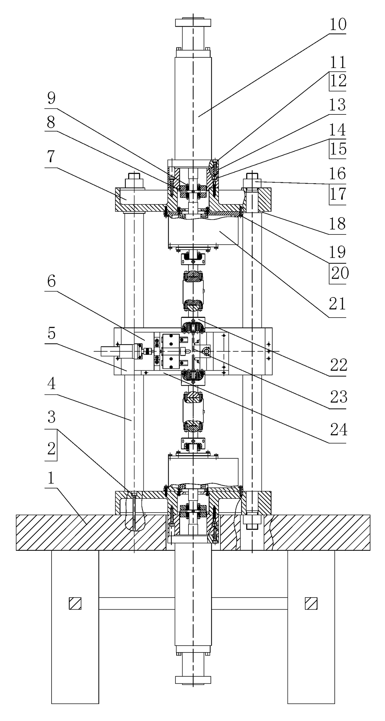
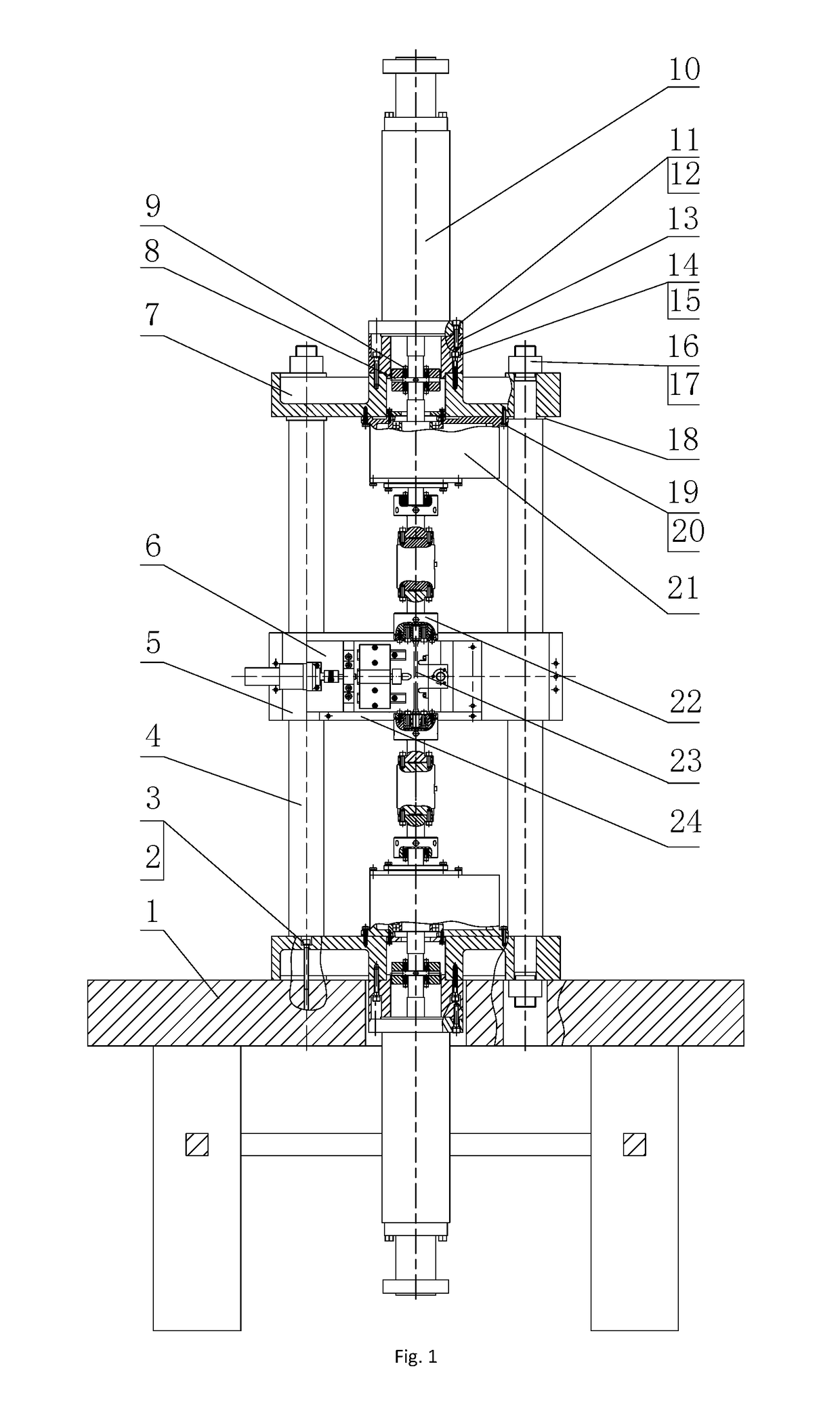
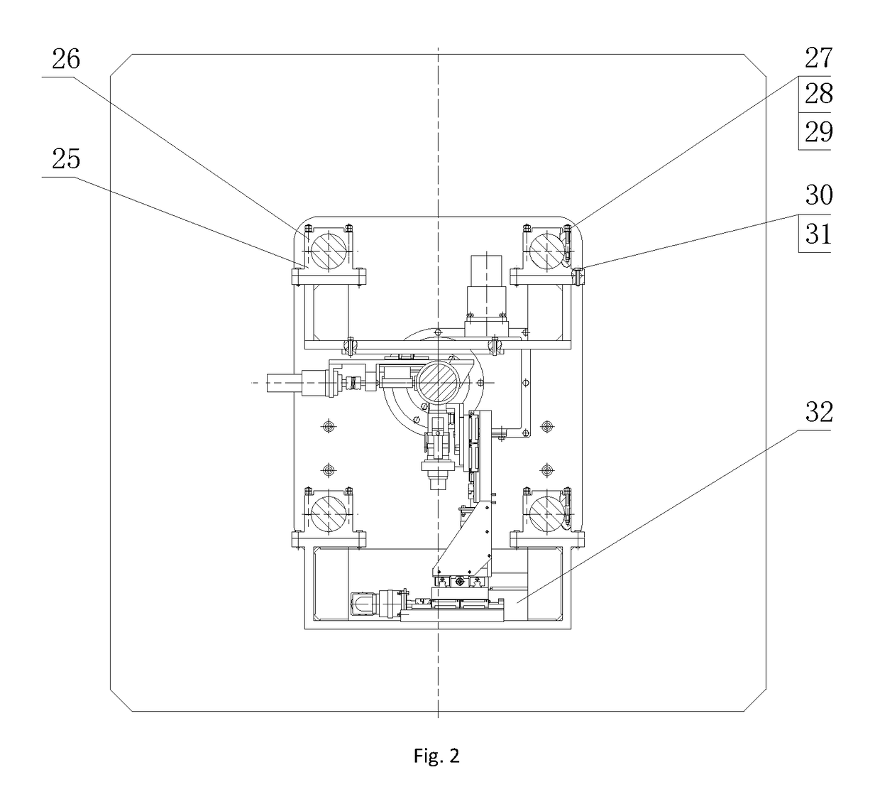
[0144]Referring to FIG. 1 to FIG. 11, an in-situ testing equipment according to an embodiment of the invention, which is configured for testing micromechanical properties of material in a multi-load and multi-physical field coupled condition, and comprises a frame supporting module, a tension / compression-low cycle fatigue module, a torsioning module 21, a three-point bending module 6, an impressing module 33, a thermal field and magnetic field application module 34, an in-situ observation module 32 and a clamp body module. The frame supporting module provides a structure support for the whole testing equipment; the tension / compression-low cycle fatigue module is arranged at upper and lower ends of the testing equipment, the torsioning module 21 is directly arranged at a front end of the tension / compression-low cycle fatigue module; the three-point bending module 6,...


PUM

PropertyMeasurementUnit
tension/compressionaaaaaaaaaa
thermal fieldaaaaaaaaaa
magneticaaaaaaaaaa

Abstract

An in-situ testing equipment for testing micromechanical properties of a material in a multi-load and multi-physical field coupled condition is disclosed. The equipment comprises a frame supporting module, a tension / compression-low cycle fatigue module, a torsioning module (21), a three-point bending module (6), an impressing module (33), a thermal field and magnetic field application module (34), an in-situ observation module (32) and a clamp body module (22). The testing equipment is capable of realizing applications of five different types of loads including tension / compression, low cycle fatigue, torsion, bending and impressing, performing an intensive study on micromechanical properties of the material in the multi-load and multi-physical field coupled condition by using built-in electric, thermal and magnetic application modules and the in-situ observation module, and acquiring relations between deformation behavior, mechanism of damage, performance weakening of the material, applied loads and material properties.

Description

PRIORITY APPLICATIONS[0001]This application is a U.S. National Stage Filing under 35 U.S.C. 371 from international Application No. PCT / CN2014 / 072805, filed on 3 Mar. 2014, and published as WO 2015 / 043137 on 2 Apr. 2015, which claims the benefit of priority to Chinese Application No. 310444251.4, filed on 26 Sep. 2013; which applications and publication are incorporated herein by reference as if reproduced herein and made a part hereof in their entirety, and the benefit of priority of each of which is claimed herein.TECHNICAL FIELD[0002]Embodiments of the present application relate to field of mechanical test of materials, particularly, to a testing equipment for testing micromechanical properties of materials, and more particularly, to an in-situ testing equipment for testing micromechanical properties of materials in a multi-load and multi-physical field coupled condition. The equipment may apply a single load selected from a group consisted of tension / compression, low cycle fatigu...

Claims


Application Information

Patent Timeline
Patent Type & Authority Patents(United States)
IPC IPC(8): G01N3/06G01N3/20G01N3/08G01N3/22G01N3/26G01N3/04G01N3/32
CPCG01N3/06G01N3/04G01N3/08G01N3/32G01N3/22G01N3/26G01N3/20
Inventor ZHAO, HONGWEIREN, LUQUANLI, JIANPINGHUANG, HUZHANG, PANFENGHU, XIAOLICHENG, HONGBINGFANG, DAININGMA, ZHICHAOZHUANG, QINGWEIGAO, JINGDONG, XIAOLONGTANG, KEHONGZHANG, FUZOU, QINGZHU, YUXIANGDONG, JINGSHIFAN, ZUNQIANGHU, YONGSHANG, TAO
Owner JILIN UNIV
Why Eureka
Try Eureka