
Surge protection device, comprising at least one surge arrester and one short-circuit switching device which is connected in parallel with the surge arrester, can be thermally tripped and is spring-pretensioned

a surge protection and short-circuit switching technology, which is applied in the direction of overvoltage protection resistors, emergency protective arrangements for limiting excess voltage/current, spark gap details, etc., can solve the problems of surge-limiting components total failure or partial failure, short-circuit current, and tripping or shutdown behavior which is not, so as to reduce the transfer resistance and expand the current transfer area

Active Publication Date: 2018-07-03
DEHN SOHNE GMBH CO KG
View PDF21 Cites 1 Cited by
  • Summary
  • Abstract
  • Description
  • Claims
  • Application Information

AI Technical Summary

Benefits of technology

The patent text is suggesting that the surfaces of the contact parts in a switching device can be designed to increase the area where current can flow and decrease the resistance to this flow. This results in a more efficient transfer of electricity.

Problems solved by technology

The solutions described in the above-mentioned prior art have a tripping or shutdown behavior which is not adapted to the special properties of the respective surge arrester used, for example, varistors.
Cases of overload and / or fault of surge arresters can, as a result of practical experience, also result in total failure or partial failure of the surge-limiting components.
The combination of surge protection devices with fuse and / or mechanical switching device has the disadvantage that, for these elements to respond and / or trip, a short-circuit current in the meaning of multiple times the rated current of the switching device or fuse has to flow.
This current, which is generally several hundred amperes or extends into the kiloampere range, can result in the destruction or explosion of the surge-limiting components and can represent a risk of fire for the device itself or for adjacent devices.
Thus, if the occurring fault current in a surge protection device is greater than that which can be extinguished by the thermal disconnection device itself, but is less than the tripping current of backup protection devices, for example, a fuse, the arrester can then be destroyed with the above-mentioned consequences.

Method used


Image

  • Surge protection device, comprising at least one surge arrester and one short-circuit switching device which is connected in parallel with the surge arrester, can be thermally tripped and is spring-pretensioned
  • Surge protection device, comprising at least one surge arrester and one short-circuit switching device which is connected in parallel with the surge arrester, can be thermally tripped and is spring-pretensioned
  • Surge protection device, comprising at least one surge arrester and one short-circuit switching device which is connected in parallel with the surge arrester, can be thermally tripped and is spring-pretensioned

Examples


Embodiment Construction

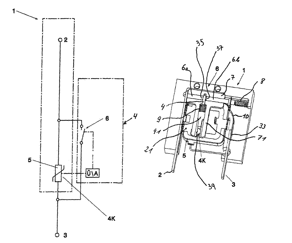
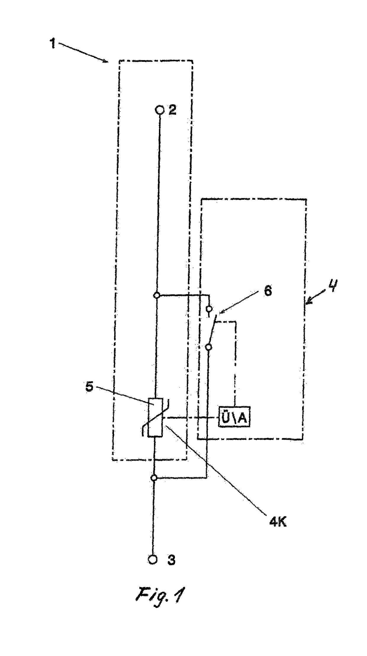
[0039]The illustration of the schematic circuit diagram according to FIG. 1 proceeds from a surge protection means 1, in which the operating-impulse current path and the monitoring path U are functionally separated. The integrated switching device 6 is designed as a short-circuiter, wherein the surge arrester, for example, designed as a varistor, is identified with the reference sign 5. The unlocking of the switching device 6 is symbolized by the reference sign 4 in FIG. 1 and the thermal coupling element is identified as the thermal tripping means with 4K. The terminals of the surge protection means have the reference signs 2 and 3.

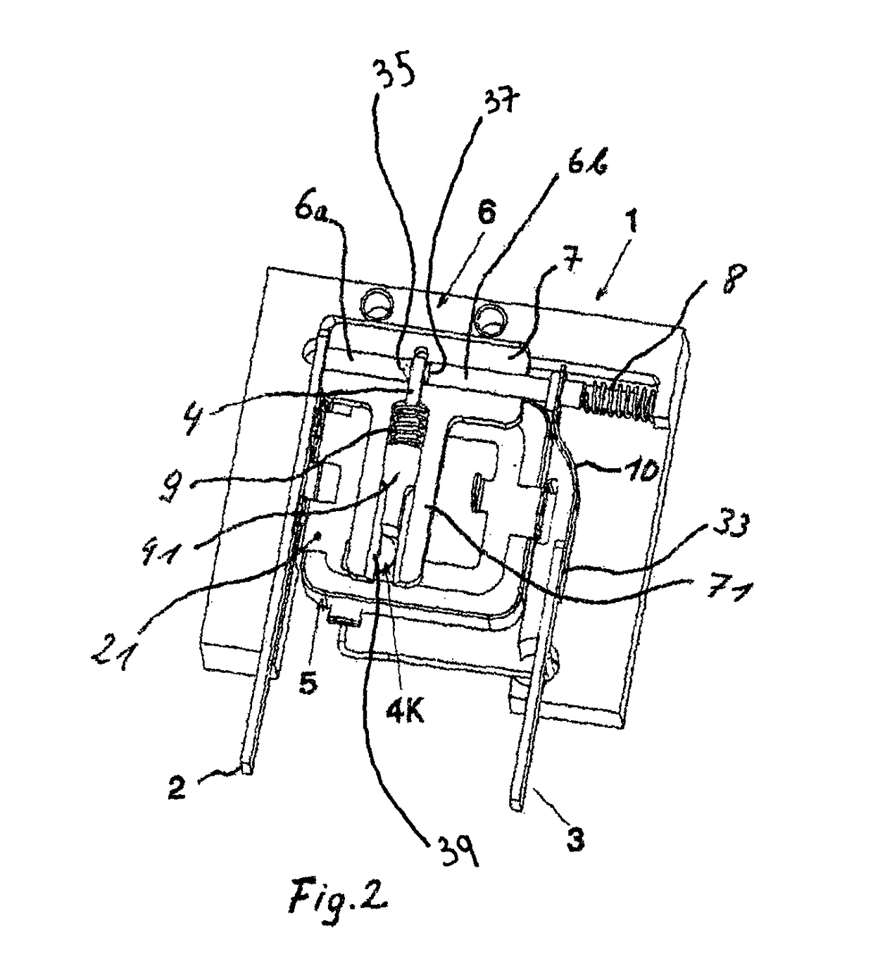
[0040]The plug part implemented according to the invention comprises the surge protection device 1 having the surge arrester 5, the unlocking slide 4, and the molded body 7, which accommodates the switching device 6 having the contact parts 6a, 6b. In addition, plug contacts 2; 3 for the operating current supply are provided on the lower side of the plug...


PUM


Abstract

The invention relates to a surge protection device, comprising at least one surge arrester and one short-circuit switching device which is connected in parallel with the surge arrester, can be thermally tripped and is spring-pretensioned, wherein the abovementioned means form one physical unit. The thermal tripping means is arranged in the region where heating of the surge arrester is expected when it is overloaded, and operating or surge current does not flow through said thermal tripping means. The thermal tripping means is in the form of a stop part which releases an unlocking slide of the switching device in the event of thermal overload. The switching device has two opposite contact pieces, wherein at least one of the contacts is of moveable design and is under spring pretension in the closing direction of the switching device. The opening state of the switching device is maintained by the unlocking slide, which is released by the thermal tripping means to close the switching device.

Description

CROSS-REFERENCE TO RELATED APPLICATIONS[0001]Not ApplicableSTATEMENT REGARDING FEDERALLY SPONSORED RESEARCH OR DEVELOPMENT[0002]Not ApplicableTHE NAMES OF THE PARTIES TO A JOINT RESEARCH AGREEMENT[0003]Not ApplicableINCORPORATION-BY-REFERENCE OF MATERIAL SUBMITTED ON A COMPACT DISC OR AS A TEXT FILE VIA THE OFFICE ELECTRONIC FILING SYSTEM (EFS-WEB)[0004]Not ApplicableSTATEMENT REGARDING PRIOR DISCLOSURES BY THE INVENTOR OR A JOINT INVENTOR[0005]Not ApplicableBACKGROUND OF THE INVENTION(1) Field of the Invention[0006]The invention relates to a surge protection device, comprising at least one surge arrester and one short-circuit switching device which is connected in parallel with the surge arrester, can be thermally tripped, and is spring-pretensioned, wherein the above-mentioned means form a module, the thermal tripping means is arranged in the region of the heating to be expected of the surge arrester in the event of the overload thereof and is designed as a stop part, through whic...

Claims


Application Information

Patent Timeline
Patent Type & Authority Patents(United States)
IPC IPC(8): H01C7/12H01T1/14H01H37/36H01H37/64H01H37/32H01H37/76H01H83/10H02H9/04
CPCH01C7/126H01C7/12H01H37/32H01H37/64H01T1/14H01H37/76H02H9/043H01H83/10H01H2037/762H01H2235/01
Inventor HIRSCHMANN, HELMUTWITTMANN, GEORGZAUNER, EDMUND
Owner DEHN SOHNE GMBH CO KG
Learn More