Vascular plug

a technology of vascular plugs and plugs, applied in the field of vascular plugs, can solve the problems of unsuitable design for the treatment site, risk of migration of the plug, and imprecise occlusion, and achieve the effects of optimizing occlusion, minimizing migration risk, and short footprin

Active Publication Date: 2018-07-10
COOK MEDICAL TECH LLC
View PDF20 Cites 2 Cited by
  • Summary
  • Abstract
  • Description
  • Claims
  • Application Information

AI Technical Summary

Benefits of technology

[0009]This structure of vascular plug is such that in the compressed form it has a short footprint and thus can be positioned in a narrow section of vessel and with precision. Furthermore, as explained below, the plug is able to expand to a variety of diameters, thus making it suitable for deployment in a range of vessel sizes. Moreover, the structure provides for continuous generation of an expansion force, which can assist in holding the plug properly against the vessel wall, thus optimizing occlusion and minimizing the risk of migration.
[0010]Preferably, the at least one resilient frame element is in the form of a ring to which the cover is fitted. A ring shape provides a strong support frame to the plug and is also readily twistable for folding.
[0011]Advantageously, the first frame element is constrained into a curved shape. Such a shape can be optimal for deployment in a patient's vessel and to provide good patency to the vessel wall.

Problems solved by technology

While such designs of plug can optimize the delivery of the plug through the patient's vasculature, particularly where this is tortuous and / or narrow, a plug which expands from an elongate form to a shorter form cannot be positioned precisely in a patient's vessel, which can make such designs unsuitable when the treatment site is short, for example between closely located branch vessels and so on.
Even with selection of a plug of the correct size, changes in the dimensions or shape of a vessel over time can cause imprecise occlusion and risk of migration of the plug.

Method used


Image

  • Vascular plug
  • Vascular plug
  • Vascular plug

Examples


Embodiment Construction

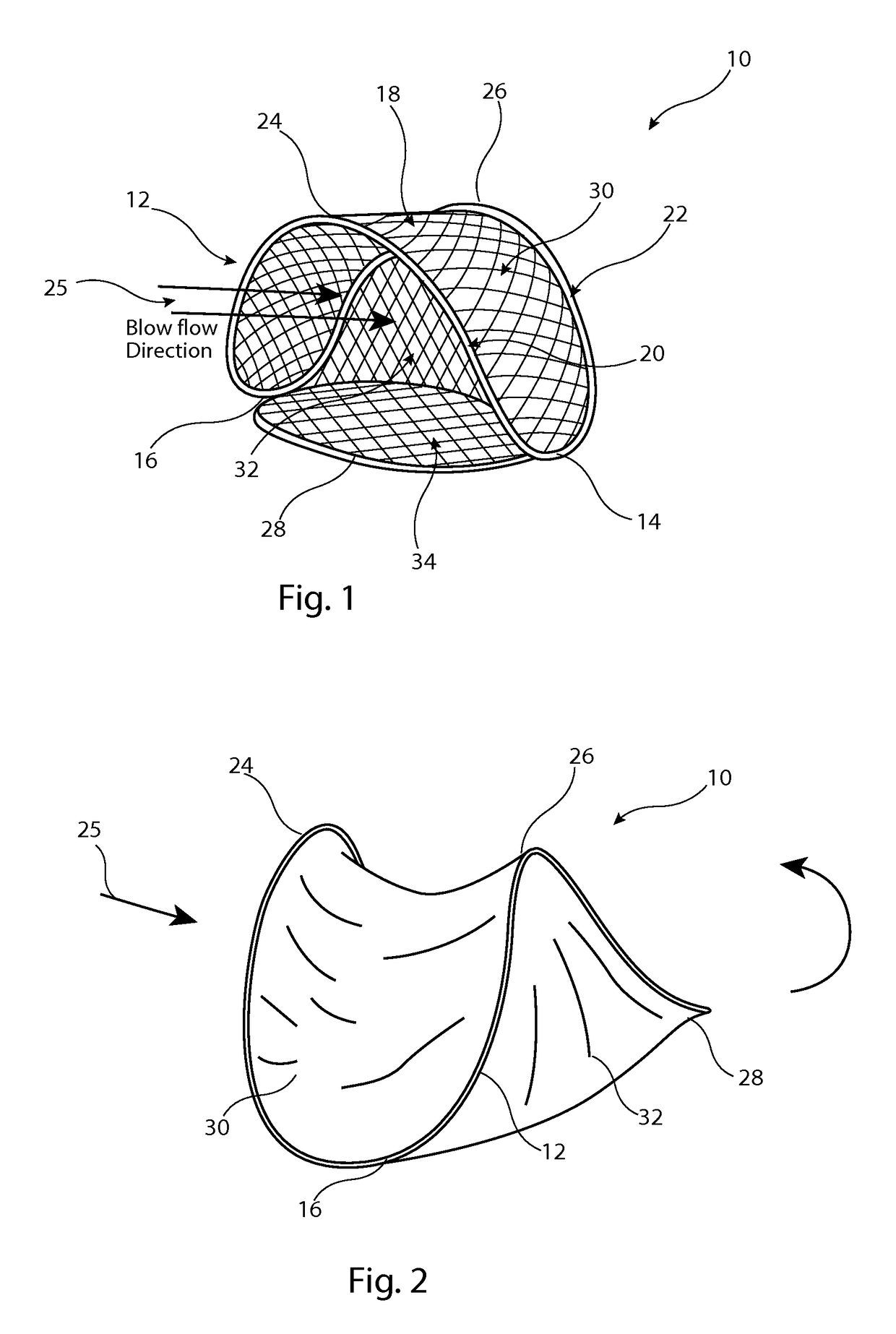
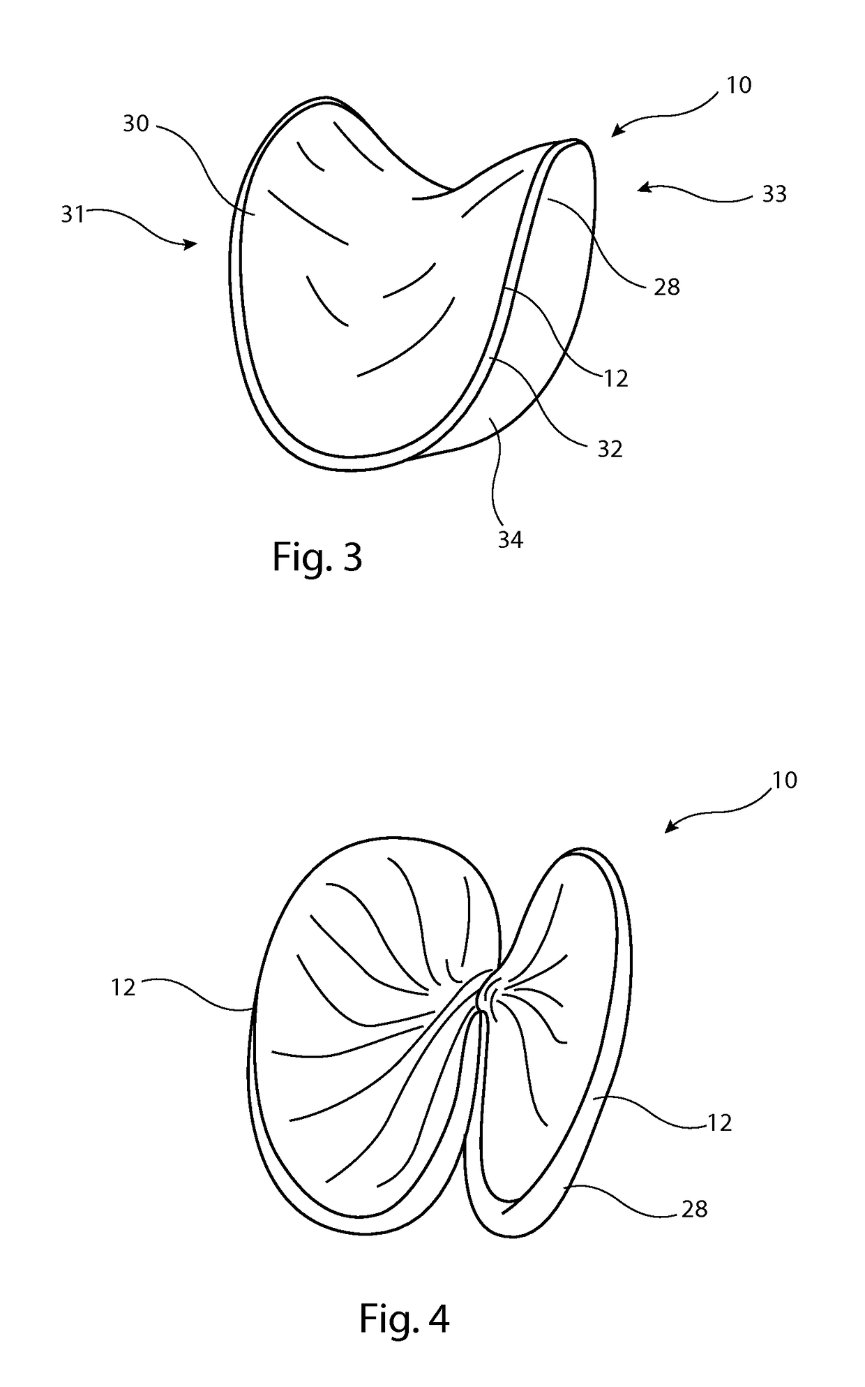
[0029]The preferred embodiments disclosed herein relate to a vascular plug which is intended to be used for embolization, that is as a device deployed in a patient's vessel to occlude the vessel, arrest or prevent hemorrhaging or devitalizing a structure or organ by occluding its blood supply. The device can be used, for example, to stop blood flow to tumors, into aneurysms, to stop blood flow to organs prior to their removal and to stop abnormal blood flow such as arteriovenous malformation (AVM) or arteriovenous fistula (AVF), for stopping bleeding and so on.

[0030]The device may provide instantaneous occlusion of a vessel, for which purpose the vascular plug is designed so as to be substantially impervious and to stop all of or practically all of the flow of blood past the plug substantially immediately on deployment of the plug. In other embodiments, the plug may be porous and designed so as to slow the flow of blood through the plug, promoting embolization and resultant occlusio...


PUM


Abstract

A vascular plug has a frame or skeleton which includes a ring of spring material and, attached to the frame, a cover of impervious or porous material. The plug is able to open a cup configuration when in a deployed condition, so as to provide an occlusion barrier to blood flow. The frame can be radially contracted by twisting into a multi-coiled configuration for deployment through an introducer. The vascular plug has a very short deployment length, making it suitable for deployment in precise locations and is also able to expand to a variety of operating diameters, thereby being suitable for a range of vessel sizes.

Description

CROSS REFERENCE TO RELATED APPLICATIONS[0001]This application is related to and claims the benefit of priority to British patent application number GB 1307965.2, filed May 2, 2013, and British patent application number GB 1316157.5, filed Sep. 11, 2013, which are incorporated herein by reference in their entireties.TECHNICAL FIELD[0002]The present invention relates to a vascular plug and to an introducer assembly including a vascular plug.BACKGROUND ART[0003]Vascular plugs, or occluders, are well known for occluding bodily vessels and are produced in a variety of forms. They may act to create substantially instantaneous occlusion of a vessel, in which case the structure of the plug provides an impermeable barrier to fluid, or they may act to occlude the vessel over time, in which case the plug will generally have a pervious membrane designed to slow the flow of blood through the vessel. The membrane promotes thrombosis of the blood and eventual occlusion of the vessel by the formed ...

Claims


Application Information

Patent Timeline
Patent Type & Authority Patents(United States)
IPC IPC(8): A61B17/08A61F2/01A61B17/12
CPCA61B17/12109A61B17/12031A61B17/12172A61B17/12177A61F2/01A61F2230/0095A61F2002/011A61F2002/016A61F2230/001A61F2230/0008A61F2230/0091A61B2017/1205A61F2/0105A61F2/011A61B17/1204A61B17/1214
Inventor HANSEN, CHRISTINA RAUFF
Owner COOK MEDICAL TECH LLC
Why Eureka
Try Eureka