Fingerprint identification apparatus and manufacturing method thereof

a fingerprint identification and manufacturing method technology, applied in the field of photoelectric devices, can solve the problems of high assembling cost, difficult fingerprint identification, and complicated assembling of conventional fingerprint identification apparatus, and achieve the effect of excellent performan

Active Publication Date: 2018-07-10
GINGY TECH
View PDF5 Cites 7 Cited by
  • Summary
  • Abstract
  • Description
  • Claims
  • Application Information

AI Technical Summary

Benefits of technology

[0006]The invention is directed to a fingerprint identification apparatus, which has a excellent performance.
[0007]The invention is directed to a manufacturing method of a fingerprint identification apparatus, by which the fingerprint identification apparatus is easily assembled.
[0022]According to the above description, in the fingerprint identification apparatus of the invention, the tilted side wall of the light guide device guides the light for propagating toward a center of the opening of the light guide device. In this way, the finger of the user is uniformly irradiated by sufficient light, such that the image capturing device may obtain clear fingerprint image to facilitate fingerprint identification.
[0023]Moreover, in the manufacturing method of the fingerprint identification apparatus of the invention, the light-emitting device is disposed on the circuit board and disposed beside the image capturing device, and the light guide device and the reflecting device are sequentially disposed and fixed on the circuit board to complete the fingerprint identification device. In this way, the assembling difficulty and assembling cost of the fingerprint identification apparatus are decreased.

Problems solved by technology

The conventional fingerprint identification apparatus is not only complicate and difficult in assembling; assembling cost thereof is also higher.
Moreover, a light-emitting device of the conventional fingerprint identification apparatus is a point light source, and if the light emitted by the point light source is diffused without optical processing, it may cause uneven distribution of the light irradiating the finger, and accordingly cause blur of a fingerprint image, which results in difficulty in fingerprint identification.

Method used


Image

  • Fingerprint identification apparatus and manufacturing method thereof
  • Fingerprint identification apparatus and manufacturing method thereof
  • Fingerprint identification apparatus and manufacturing method thereof

Examples


Embodiment Construction

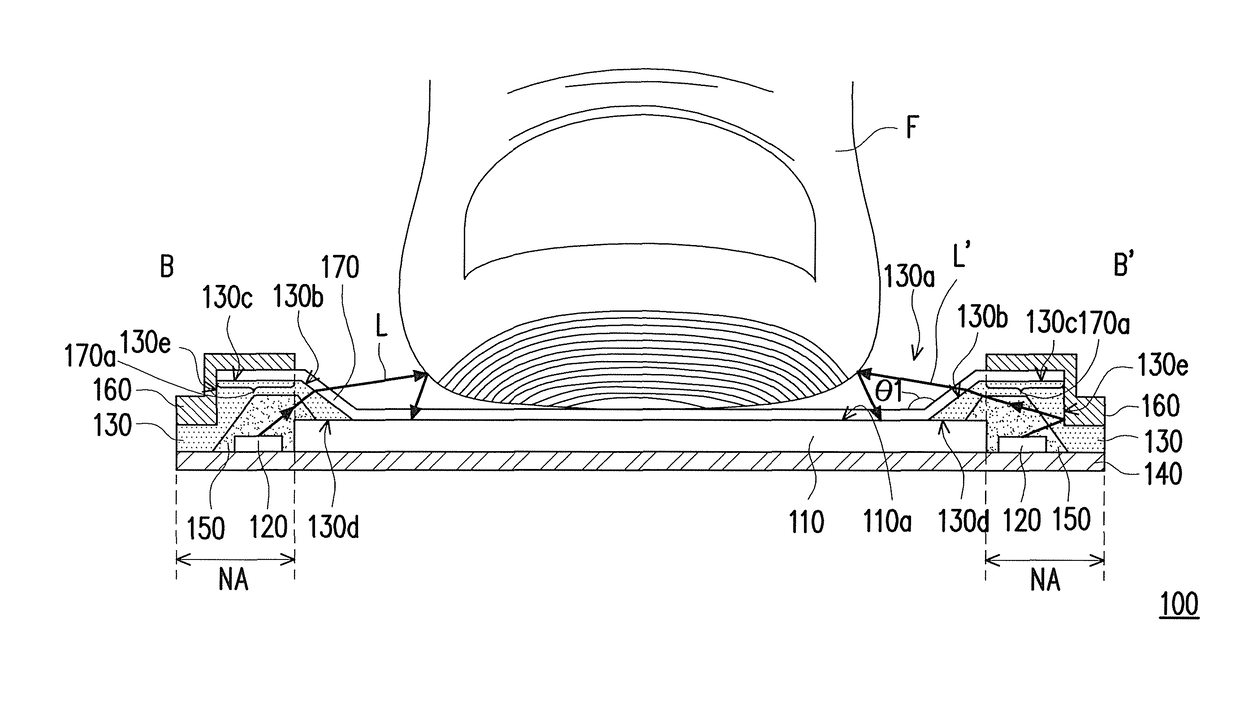
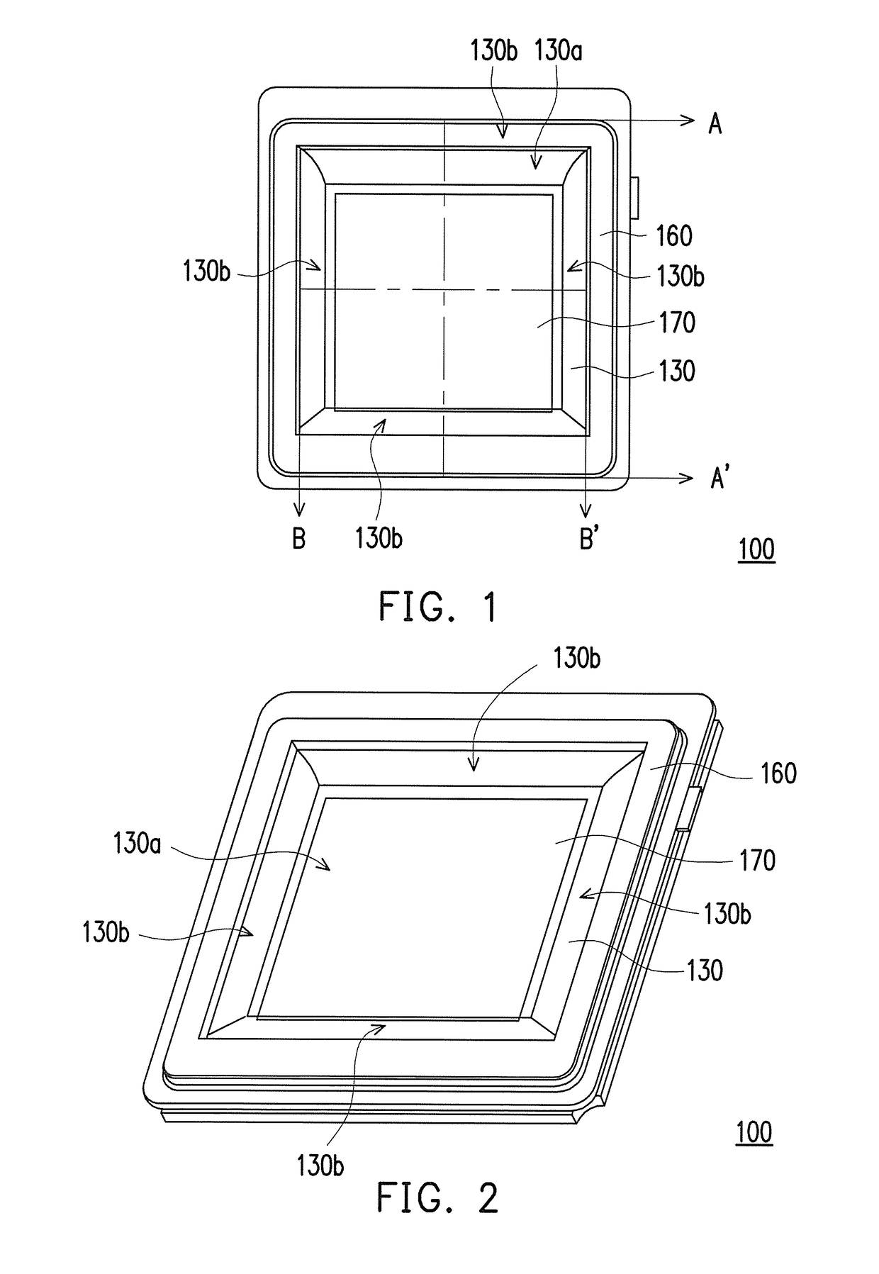
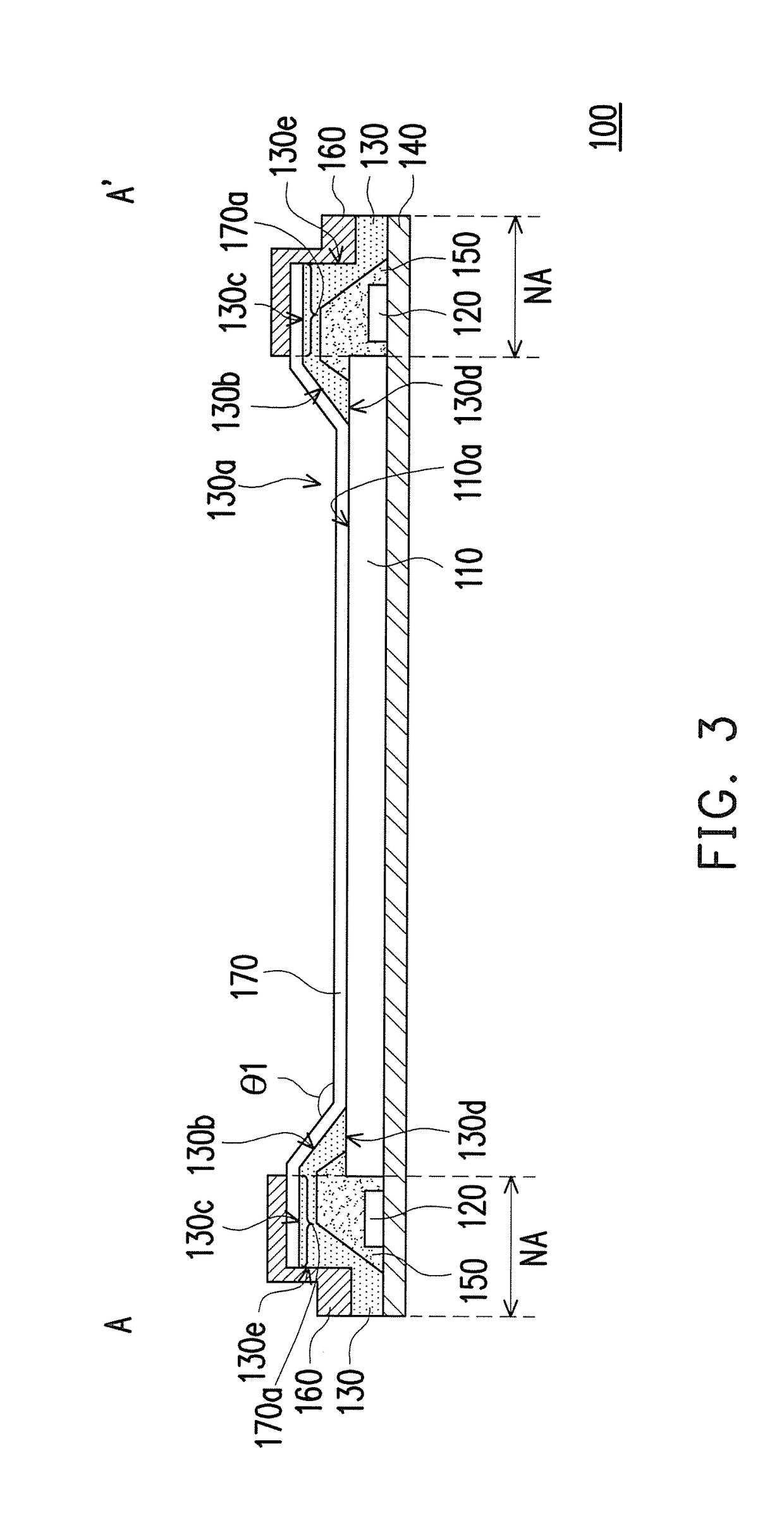
[0035]FIG. 1 is a top view of a fingerprint identification apparatus according to an exemplary embodiment of the invention. FIG. 2 is a three-dimensional view of the fingerprint identification apparatus of FIG. 1. FIG. 3 is a cross-sectional view of the fingerprint identification apparatus of FIG. 1 viewing along a section line A-A′. FIG. 4 is a cross-sectional view of the fingerprint identification apparatus of FIG. 1 viewing along a section line B-B′. Referring to FIG. 1, FIG. 2, FIG. 3 and FIG. 4, the fingerprint identification apparatus 100 includes an image capturing device 110, at least one light-emitting device 120 and a light guide device 130. The image capturing device 110 has a light reception surface 110a. When a finger F presses the fingerprint identification apparatus 100, the light reception surface 110a of the image capturing device 110 is overlapped with the fingerprint of the finger F. The at least one light-emitting device 120 is disposed beside the image capturing...


PUM


Abstract

A fingerprint identification apparatus including an image capture device, at least one light emitting device and a light guide device is provided. The image capture device has a light reception surface. The at least one light emitting device is disposed beside the image capture device. The light guide device shields the at least one light emitting device and has an opening. The opening of the light guide device exposes the light reception surface of the image capture device. The opening of the light guide device is defined by a side wall of the light guide device. The side wall of the light guide device is tilted relative to the light reception surface of the image capture device. Moreover, a manufacturing method of the fingerprint identification apparatus is also provided.

Description

CROSS-REFERENCE TO RELATED APPLICATION[0001]This application claims the priority benefits of U.S. provisional application Ser. No. 62 / 363,329, filed on Jul. 17, 2016, and Taiwan application serial no. 105124391, filed on Aug. 2, 2016. The entirety of each of the above-mentioned patent applications is hereby incorporated by reference herein and made a part of this specification.BACKGROUND OF THE INVENTIONField of the Invention[0002]The invention relates to a photoelectric apparatus, and particularly relates to a fingerprint identification apparatus.Description of Related Art[0003]Fingerprint identification apparatuses can be divided into optical, capacitive, ultrasonic and thermal sensing type fingerprint identification apparatuses. Taking the optical fingerprint identification apparatus as an example, the conventional optical fingerprint identification apparatus includes an optical assembly and an image capturing device. The optical assembly is used for transmitting lights. The opti...

Claims


Application Information

Patent Timeline
Patent Type & Authority Patents(United States)
IPC IPC(8): G06K9/28G06K9/00G06V30/144G06V40/14
CPCG06K9/0004G06K9/00046G06K9/0008G06V40/1318G06V40/14G06V40/40G06V40/1324G06V40/1359G06V40/1365G06F18/00
Inventor WU, JEN-CHIEH
Owner GINGY TECH
Why Eureka
Try Eureka