
Hyper-velocity penetrating probe for spectral characterization

a hyper-velocity, probe technology, applied in the direction of ammunition fuzes, target detectors, instruments, etc., can solve the problems of inefficient method that does not satisfactorily reduce or eliminate uncertainties, and high degree of uncertainty as to the circumstances of impact, etc., to achieve efficient or optimal use of resources and high degree of uncertainty

Active Publication Date: 2018-07-17
RAYTHEON CO
View PDF6 Cites 3 Cited by
  • Summary
  • Abstract
  • Description
  • Claims
  • Application Information

AI Technical Summary

Benefits of technology

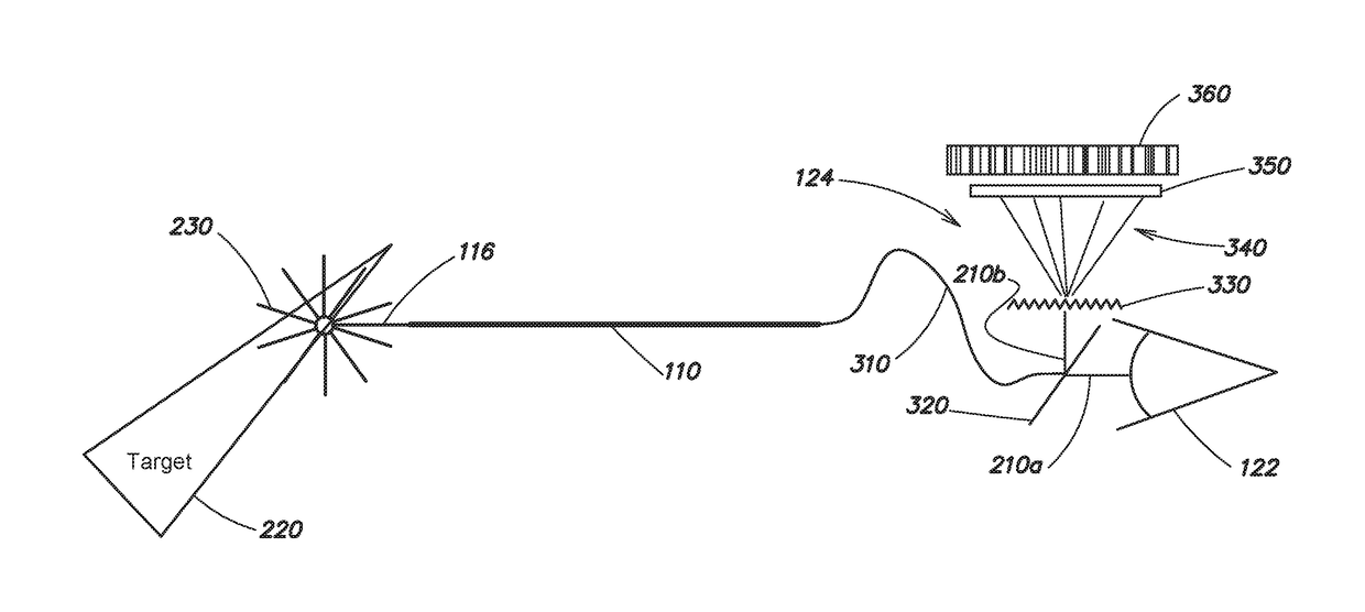
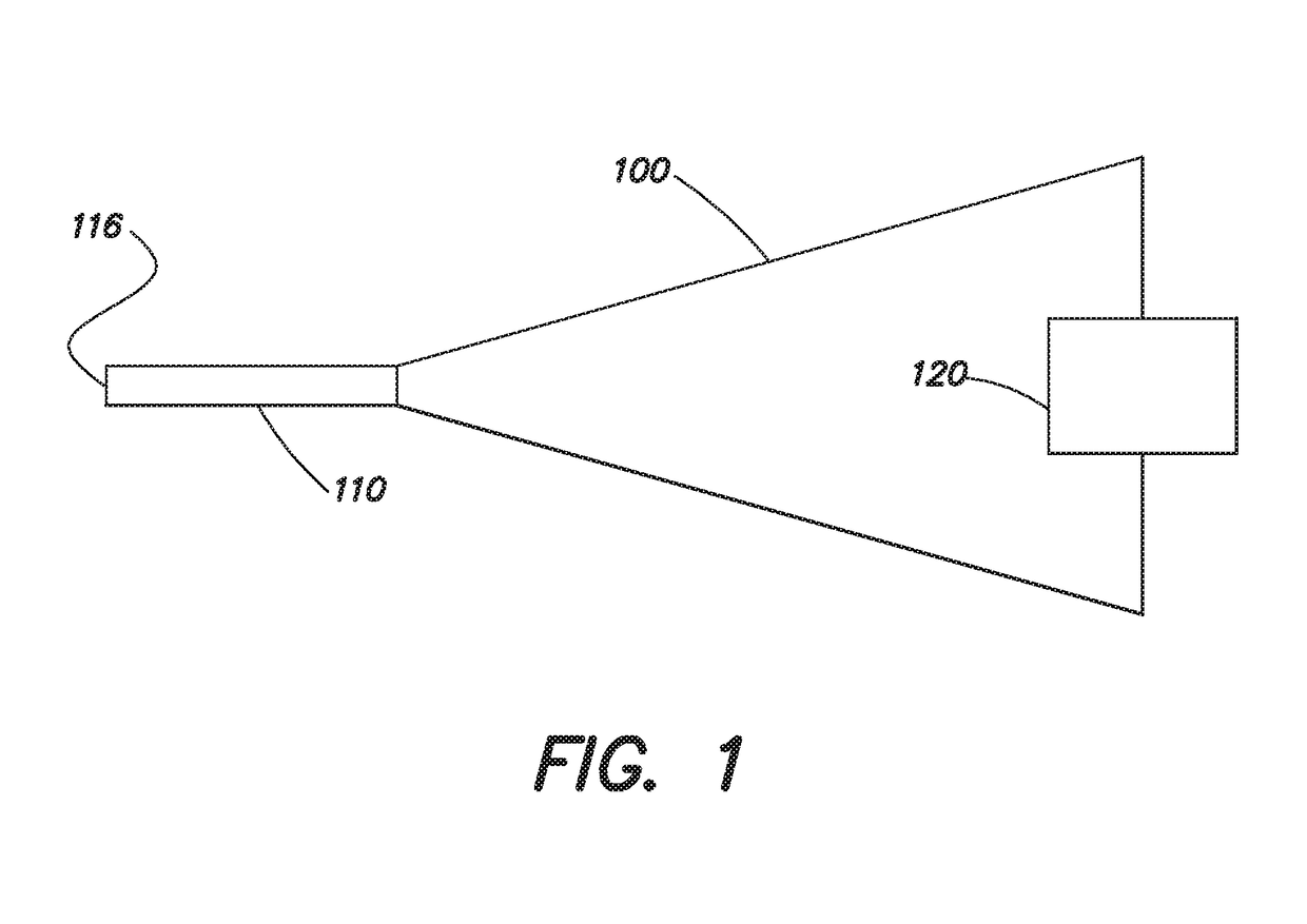
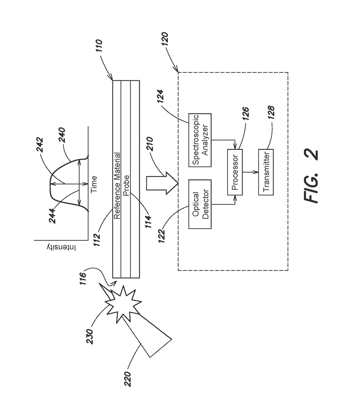
The patent text describes a new type of impact sensor that can detect and analyze the chemical composition of an object that is hit with a high-velocity projectile. This sensor uses an optical fiber probe to transmit an optical pulse and a dispersive element to spectrally disperse the pulse. A photosensitive detector records the spectral information, which is then analyzed by a processor to identify the chemical element or compound in the object. The sensor can be used in various applications such as threat neutralization, where the goal is to determine if the threat was successfully hit or not. The technical effect of this sensor is that it provides a more definitive and accurate way to identify the target and assess the impact, which can help to improve efficiency and reduce uncertainty.

Problems solved by technology

Even though certain impact sensors provide the ability to detect and report ultra-high velocity impacts, there still can be a high degree of uncertainty as to the circumstances of the impact.
However, these methods do not satisfactorily reduce or eliminate the uncertainties.
Furthermore, due to the data latencies involved in determining whether the threat was hit and destroyed, it can be necessary to deploy multiple kill vehicles per threat, which may not be an efficient or optimal use of resources.

Method used


Image

  • Hyper-velocity penetrating probe for spectral characterization
  • Hyper-velocity penetrating probe for spectral characterization
  • Hyper-velocity penetrating probe for spectral characterization

Examples


Embodiment Construction

[0017]As discussed above, hyper-velocity impact sensors can be used to detect and report ultra-high velocity collisions between a projectile, such as a kinetic energy weapon or so-called kill vehicle, and a target. In particular, an optical fiber impact sensor can be used to detect and transmit certain information about the impact before the sensor is destroyed. However, guaranteed kill assessment of threats (i.e., determination with certainty that the threat was destroyed or neutralized) cannot be achieved using conventional approaches and technologies. Uncertainties in discrimination of threats versus other objects, and the data latencies between the time of the impact and the time at which an acceptably accurate determination can be made as to the identity of the impacted target and result of the impact (e.g., was the target destroyed) are prohibitive.

[0018]Aspects and embodiments are directed to a hyper-velocity impact sensor system that includes an optical fiber hyper-velocity ...


PUM


Abstract

A hyper-velocity impact sensor including an optical fiber probe that transmits an optical pulse generated during impact with an object, a spectroscopic analyzer that receives the optical pulse and produces spectral information about the optical pulse, a connecting optical fiber configured to convey the optical pulse between the optical fiber probe and the spectroscopic analyzer, and at least one processor coupled to the spectroscopic analyzer and configured to receive and analyze the spectral information to determine at least one chemical element or compound contained in the object.

Description

BACKGROUND[0001]Shock and impact sensors are devices that detect sudden movements, changes, or severe impacts at a predetermined level and indicate whether that level has been exceeded. Impact sensors are used in applications where it is desirable to know when an impact has occurred. In an ultra-high velocity impact, the relative velocities of the colliding objects can be about 5000 meters per second (m / s) or higher which is about the speed of sound in metal. The speed of sound through the metal construction materials of a projectile limits the propagation speed of the shock wave from an impact through the projectile. An example of an application that uses this ultra-high velocity is an anti-projectile projectile. During the final flight stage of the projectile, high velocities are used to improve the accuracy and the efficacy of a successful engagement. In the case where it is desirable for a projectile to send a notification that it has had an impact, this event must be sensed, an...

Claims


Application Information

Patent Timeline
Patent Type & Authority Patents(United States)
IPC IPC(8): G01D5/353F42B30/00
CPCF42B30/006G01D5/353F41J5/02F42B12/365F42C13/02G01P15/093G01N21/70G01N2201/08
Inventor CRAWFORD, THOMAS M.WRIGHT, RICHARD J.SIERCHIO, JAMES G.
Owner RAYTHEON CO
Learn More