
Micromechanical component including a diffusion stop channel

a micromechanical and stop channel technology, applied in the direction of fluid speed measurement, instruments, coatings, etc., can solve the problems of not being able to vibrate the sensor, and the gas also diffraction, so as to achieve simple and cost-effective, simple and cost-effective

Active Publication Date: 2018-07-24
ROBERT BOSCH GMBH
View PDF4 Cites 3 Cited by
  • Summary
  • Abstract
  • Description
  • Claims
  • Application Information

AI Technical Summary

Benefits of technology

This approach effectively reduces particle diffusion between cavities, ensuring optimal operating conditions for both rotation rate and acceleration sensors, enhancing the mechanical robustness and service life of micromechanical components while maintaining cost-effectiveness.

Problems solved by technology

In the case of acceleration sensors, however, it is not desirable for the sensor to vibrate, which would be possible if an external acceleration were applied.
However, such gases also diffuse, for example, due to high temperatures from the sensor wafer or the cap wafer occurring during the capping process.

Method used


Image

  • Micromechanical component including a diffusion stop channel
  • Micromechanical component including a diffusion stop channel
  • Micromechanical component including a diffusion stop channel

Examples


Embodiment Construction

[0038]Identical parts are denoted by the same reference numerals in the various figures and are therefore generally also cited or mentioned only once.

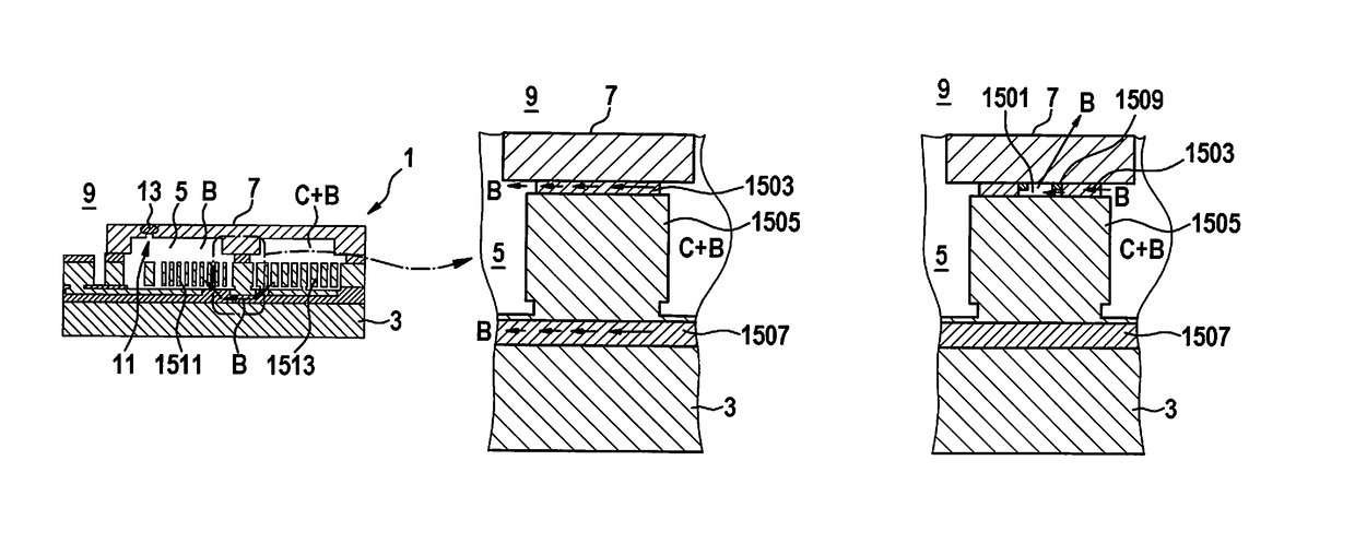
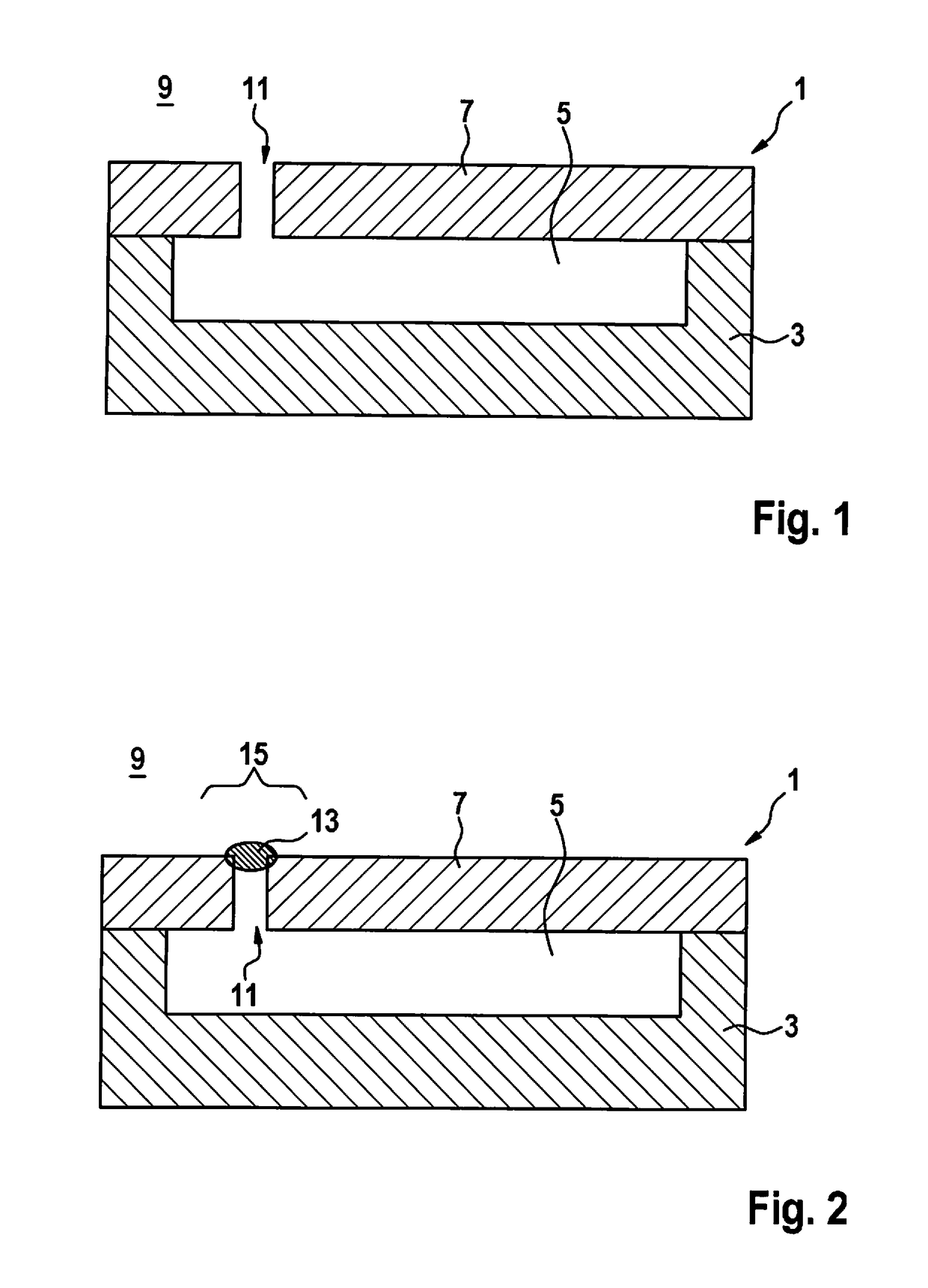
[0039]FIG. 1 and FIG. 2 show a schematic representation of a micromechanical component 1 having an open access opening 11 in FIG. 1, and having a sealed access opening 11 in FIG. 2, according to one exemplary specific embodiment of the present invention. Micromechanical component 1 includes a substrate 3 and a cap 7. Substrate 3 and cap 7 are, preferably hermetically, connected to one another and together enclose a first cavity 5. For example, micromechanical component 1 is designed in such a way that substrate 3 and cap 7 additionally together enclose a second cavity. The second cavity, however, is not shown in FIG. 1 and in FIG. 2.

[0040]For example, a first pressure prevails in first cavity 5, in particular when access opening 11 is sealed, as shown in FIG. 2.

[0041]Moreover, a first gas mixture having a first chemical composition is ...


PUM

PropertyMeasurementUnit
pressureaaaaaaaaaa
internal pressureaaaaaaaaaa
temperaturesaaaaaaaaaa

Abstract

A method for manufacturing a micromechanical component is provided including a substrate and including a cap, which is connected to the substrate and, together with the substrate, encloses a first cavity, a first pressure prevailing and a first gas mixture having a first chemical composition being enclosed in the first cavity, the cap together with the substrate enclosing a second cavity, a second pressure prevailing and a second gas mixture having a second chemical composition being enclosed in the second cavity. A recess situated essentially between the first cavity and the second cavity is formed for diverting at least one first particle type of the first gas mixture and / or at least one second particle type of the second gas mixture.

Description

CROSS REFERENCE[0001]The present application claims the benefit under 35 U.S.C. § 119 of German Patent No. DE 102016200499.9 filed on Jan. 16, 2016, which is expressly incorporated herein by reference in its entirety.BACKGROUND INFORMATION[0002]A method is described in PCT Application No. WO 2015 / 120939 A1. When a certain internal pressure is desired in a cavity of a micromechanical component or a gas mixture having a certain chemical composition is to be enclosed in the cavity, the internal pressure or the chemical composition is frequently adjusted during capping of the micromechanical component or during the bonding process between a substrate wafer and a cap wafer. During capping, for example, a cap is connected to a substrate, whereby the cap and the substrate together enclose the cavity. By adjusting the atmosphere or the pressure and / or the chemical composition of the gas mixture present in the surroundings during capping, it is thus possible to adjust the certain internal pr...

Claims


Application Information

Patent Timeline
Patent Type & Authority Patents(United States)
IPC IPC(8): B81B7/00B81C1/00
CPCB81B7/0041B81C1/00293B81B2201/0235B81B2203/0315B81C2203/0145B81B2207/09B81C2203/0109B81C2203/019B81B2207/056G01P3/26G01P15/00B81C2203/035B81B7/02B81B2201/0242B81C2203/0118
Inventor BREITLING, ACHIMREICHENBACH, FRANKREINMUTH, JOCHENAMTHOR, JULIA
Owner ROBERT BOSCH GMBH
Learn More