Electromechanical horn for deterring animals

a technology of electromechanical horns and horns, applied in the field of sound devices, can solve the problems of increasing the chances of injuries to both individuals and animals, increasing the stress on individuals, and increasing the chance of injuries to individuals and animals. , to achieve the effect of reducing the risk of injury to individuals and animals

Inactive Publication Date: 2018-08-28
STEPHENS LEAH MRS +1
View PDF23 Cites 6 Cited by
  • Summary
  • Abstract
  • Description
  • Claims
  • Application Information

AI Technical Summary

Benefits of technology

[0039]Another significant feature and advantage of this invention is that it produces a series of short, audible sound signals of different fundamental frequencies in a repetitive alternating pattern with associated harmonics in a frequency range, and at decibel levels in the region of greatest hearing sensitivity of dogs and at which of a variety of breeds and ages will respond.
[0040]Another significant feature and advantage of this invention is that may produce a series of short, one-tone audible sound signals of the same fundamental frequency in a repetitive pattern with associated harmonics in a frequency range, and at decibel levels in the region of greatest hearing sensitivity of dogs and at which of a variety of breeds and ages will respond.
[0041]Another feature and advantage of this invention is that the horn device utilizes a piezoelectric speaker for generating the high intensity of the sound which is small in size, ...

Problems solved by technology

Unfortunately, the individual or individuals may become hurt in attempting to flee or discourage the animal.
The animal may charge or attack the individuals and/or chase them causing further stress to the individuals and increasing the chances for injuries to both the individuals and the animals.
However, such devices are not effective on all dogs.
Another problem with an “ultrasonic” product marketed to deter canines is that the ultrasonic frequency does not disperse well as “beam angle” decreases as frequency increases, thus, the result can also depend upon how precisely the user aims the sound emitting device.
Another major problem with many air horns is that the pressure of the gas and thus ...

Method used


Image

  • Electromechanical horn for deterring animals
  • Electromechanical horn for deterring animals
  • Electromechanical horn for deterring animals

Examples


Embodiment Construction

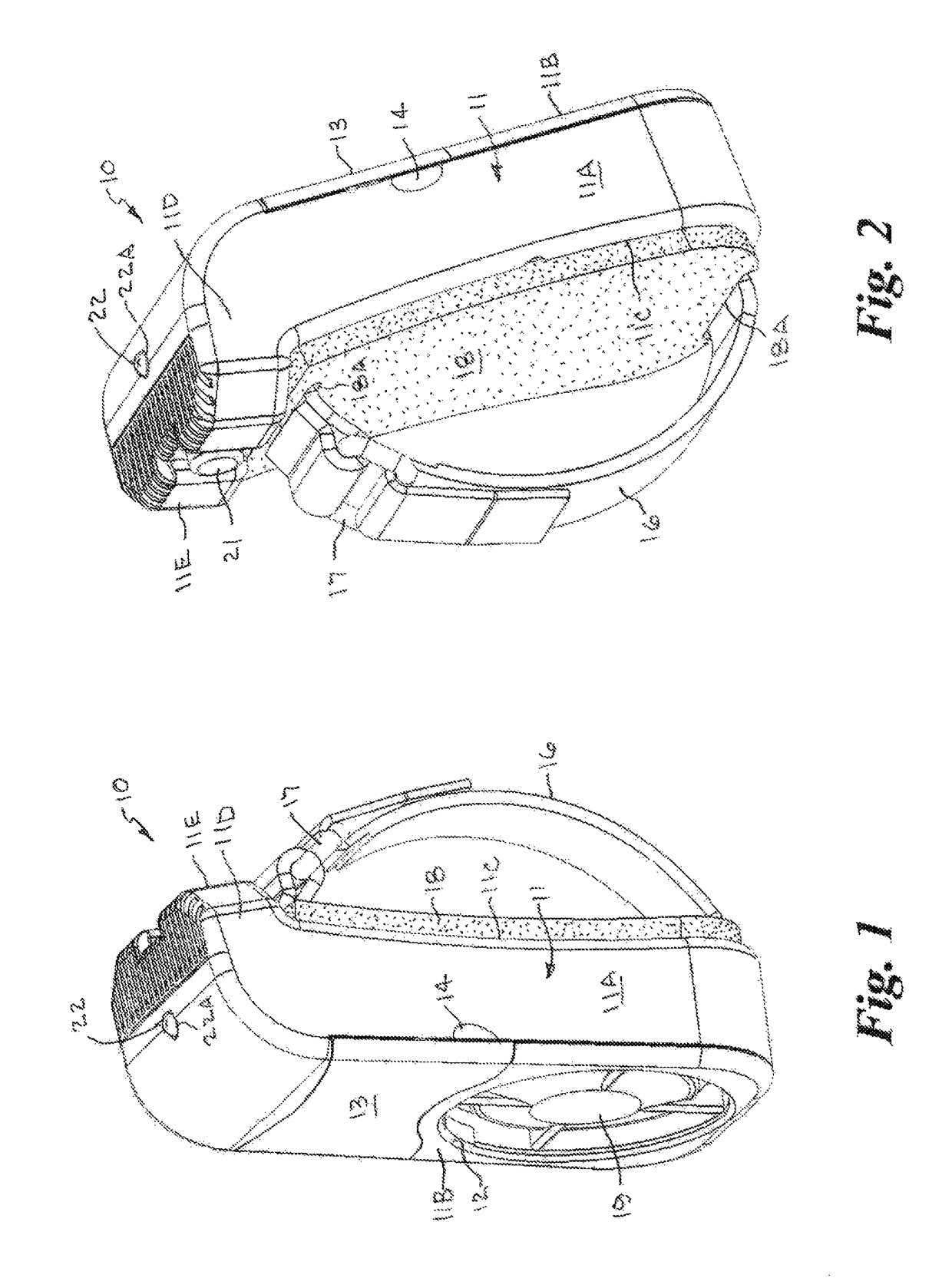
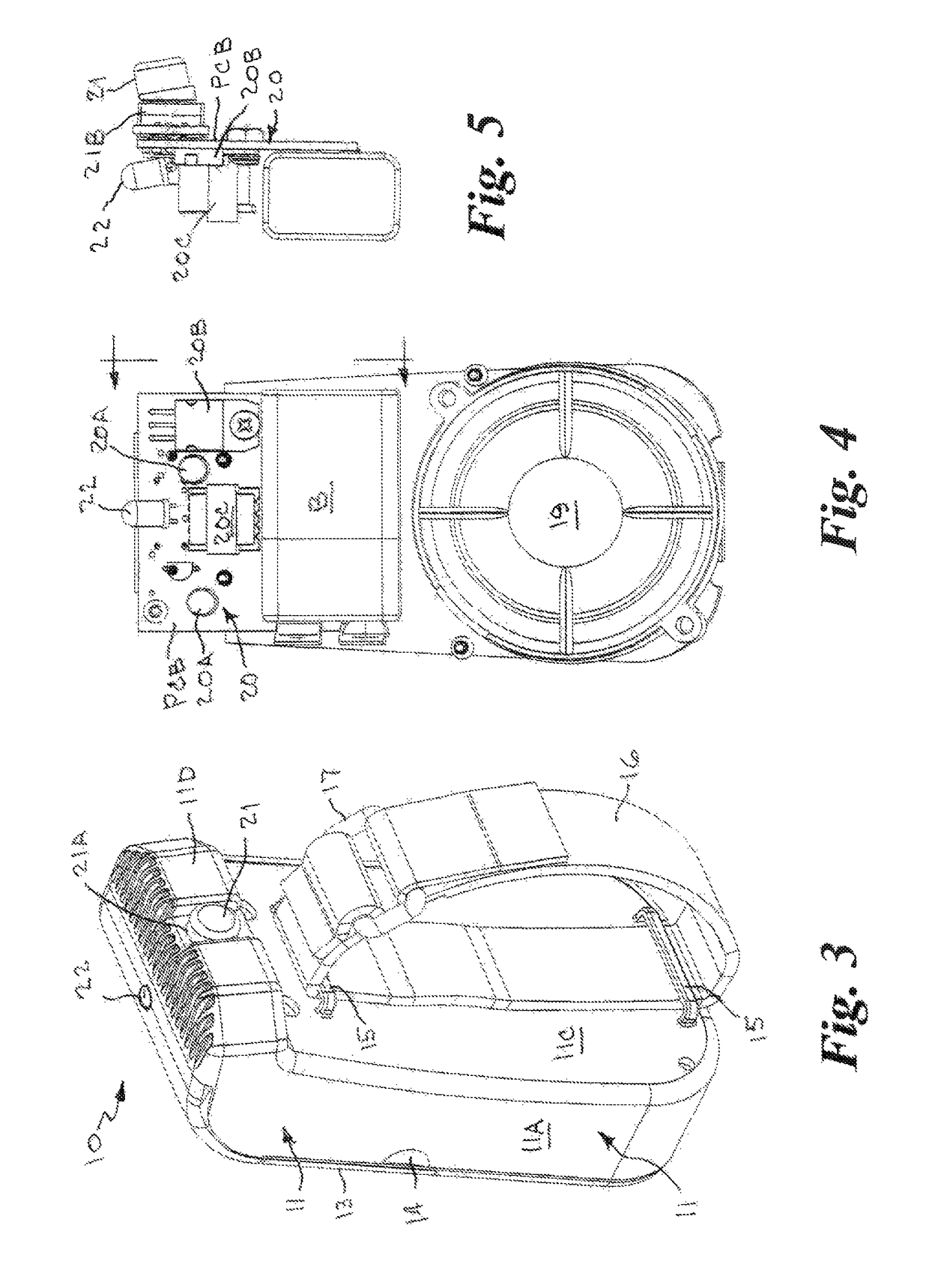
[0052]Referring to the drawings by numerals of reference, there is shown in FIGS. 1-3, an electromechanical horn device 10 in accordance with a preferred embodiment of the present invention. In the following discussion, the terms, such as top, bottom, upper, lower, inward, outward, downward, above, and below are used to describe the orientation of the horn components as depicted with the device positioned as shown in the drawings.

[0053]In the following discussion, for purposes of understanding, the following terms related to the hand of a user are given the ordinary and customary anatomical meanings attributed to them by those of ordinary skill in the art. The front, or palm-side, of the hand is referred to as the “palmar side”, and the back of the hand is called the “dorsal side”.

[0054]The horn 10 includes a generally inverted L-shaped housing 11 formed with a longer, generally rectangular lower portion 11A having a front side 11B, a back side 11C, and a shorter generally rectangul...


PUM


Abstract

An electromechanical horn having a generally L-shaped housing containing a sound generating system including a piezoelectric speaker generates a series of short, audible sound signals in a repetitive pattern, the generated sound signals having fundamental frequencies with associated harmonic component frequencies and decibel levels that fall within a frequency range of from about 3 kHz to about 10 kHz, and decibel levels in a range of from about 75 dB to about 115 dB to disperse or deter an aggressive animal in a non-detrimental manner. The lower portion of the horn is configured to be held in the palm of a hand of a user. A strap mounted on the back side of the housing forms a loop that can be grasped by the palm of the user's hand, or extended over the back of the hand, and a depressible thumb button disposed at the back end of the upper portion receives the user's thumb.

Description

CROSS REFERENCE TO RELATED APPLICATION[0001]This application is a Continuation-In-Part of and claims priority of U.S. patent application Ser. No. 13 / 548,185, filed on Jul. 12, 2012.BACKGROUND OF THE INVENTION1. Field of the Invention[0002]This invention relates generally to sound devices that are used to disperse or deter animals and, more particularly, to an electromechanical horn device that produces a very loud audible sound in a frequency range in the region of greatest hearing sensitivity of a particular animal species, such as canines, and at a decibel level and pattern specially calculated to effectively disperse or deter an aggressive animal in a non-detrimental manner.2. Background Art[0003]In the following discussion, for purposes of understanding, the following terms related to sound are given the ordinary and customary meanings attributed to them by those of ordinary skill in the art. “Frequency” refers to the “pitch” of a sound measured in Hertz (Hz) or Kilohertz (kHz)....

Claims


Application Information

Patent Timeline
IPC IPC(8): A01M29/16A01K15/02G10K9/122G05B15/02
CPCA01M29/16G10K9/122G05B15/02A01K15/021A01K15/022H04R17/00
Inventor STEPHENS, LEAHSTEPHENS, JOHNFISHER, MATTHEW T.
Owner STEPHENS LEAH MRS
Why Eureka
Try Eureka