

Method, apparatus, and article for pet attenuation correction utilizing MRI
a technology of attenuation correction and pet, applied in the field of medical diagnostic imaging, can solve problems such as easy attenuation
- Summary
- Abstract
- Description
- Claims
- Application Information
AI Technical Summary
Benefits of technology
Problems solved by technology
Method used
Image

Examples
Embodiment Construction
[0020]Reference will be made below in detail to exemplary embodiments of the invention, examples of which are illustrated in the accompanying drawings. Wherever possible, the same reference characters used throughout the drawings refer to the same or like parts, without duplicative description. Although aspects of the invention relate to attenuation correction for PET imaging, the invention more generally relates to estimation of paramagnetic structural shapes that are not directly perceptible from MRI.
[0021]Embodiments of the present invention are generally applicable to MRI, though exemplary embodiments are described with respect to multispectral 3D magnetic resonance imaging (MS 3D MRI). As will be appreciated, embodiments of the invention are not limited to human body tissue but may be used with other types of animal tissue.
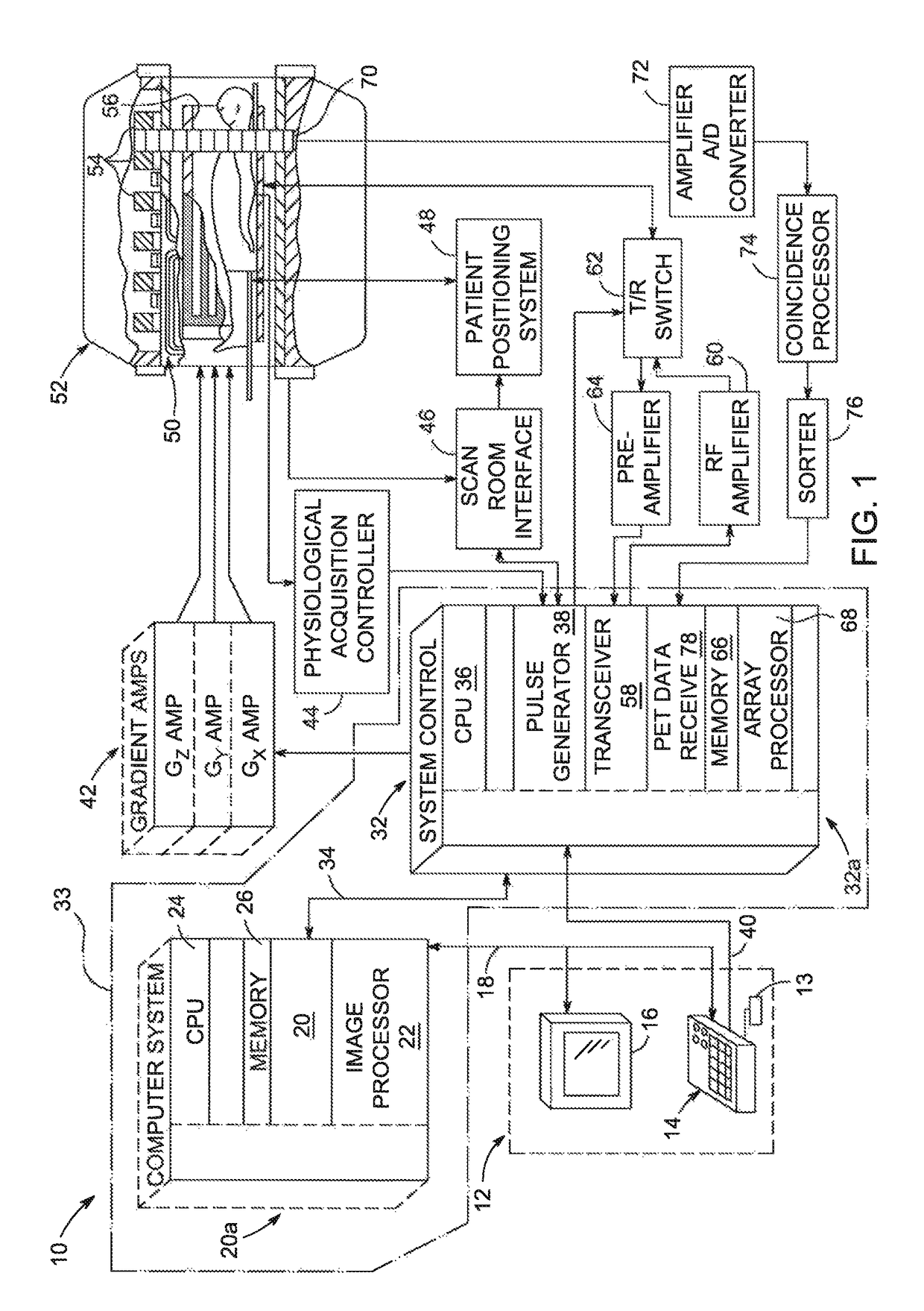
[0022]FIG. 1 shows major components of an exemplary system 10 that combines MRI with PET and is configured for use with embodiments of the present invention....
PUM
 Abstract
Description
Claims
Application Information