Optical spatial division multiplexing usable at short reach

a technology of optical spatial division and short reach, applied in the field of apparatus and methods for optical fiber communications, can solve the problems of high cost of optical components and costly data processing components in optical transport networks, and achieve the effect of high bandwidth data communication and low cos

Active Publication Date: 2018-09-11
NOKIA OF AMERICA CORP
View PDF24 Cites 1 Cited by
  • Summary
  • Abstract
  • Description
  • Claims
  • Application Information

AI Technical Summary

Benefits of technology

[0007]Some embodiments provide an optical data communication components and / or systems that are adapted for use at short reach, e.g., inside a data center and / or between nearby data centers. For example, in a data center, the optical data communication systems may provide optical data communications between different servers, between servers and top of rack switches (TORSs), between TORSs, between TORSs and other switches, between switches, between switches and routers, or more generally between data management devices of a data center. Such embodiments may provide for low cost and / or high bandwidth data communications over short optical transmission distances.

Problems solved by technology

Such optical transport networks often use costly optical components and costly data processing components, e.g., to compensate for chromatic dispersion, inter-channel and / or intra-channel interference, noise, nonlinear optical distortions, and / or optical loss.

Method used


Image

  • Optical spatial division multiplexing usable at short reach
  • Optical spatial division multiplexing usable at short reach
  • Optical spatial division multiplexing usable at short reach

Examples


embodiment 14

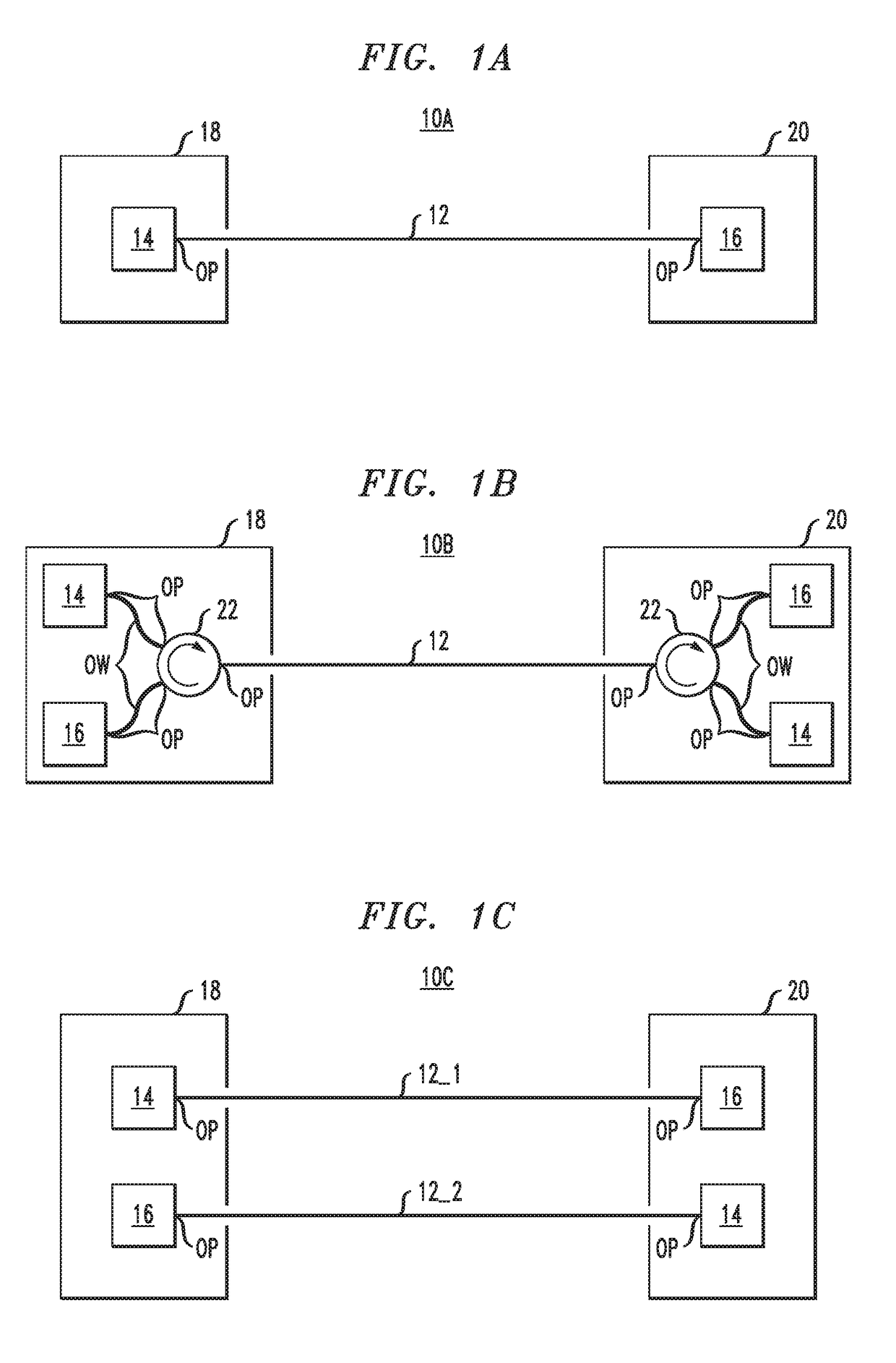
[0044]FIG. 2 schematically illustrates an embodiment 14′ of the optical data transmitter 14, which is present in one or both of the nodes 18, 20 of FIGS. 1A-1C. The optical data transmitter 14′ includes N optical sources 24_1 . . . 24_N, N corresponding electrical drivers 26_1 . . . 26_N, and an all-optical spatial mode multiplexer 28.

[0045]Each optical source 24_1-24_N is a vertical cavity surface-emitting laser (VCSEL). The different VCSELs 24_1-24_N may be configured to operate, e.g., at about the same center wavelength, e.g., less than or equal to 1.0 micrometers or even in the range of 0.7 micrometers to 0.9 micrometers. For example, the VCSELs 24_1-24_N may even output light at a center wavelength suitable for pumping conventional erbium doped optical fiber amplifiers for use in C-band optical telecommunications or may even output light at a shorter center wavelength, e.g., a wavelength between 0.80 and 0.70 micrometers, which is suitable for pumping other conventional lasers....

embodiment 16

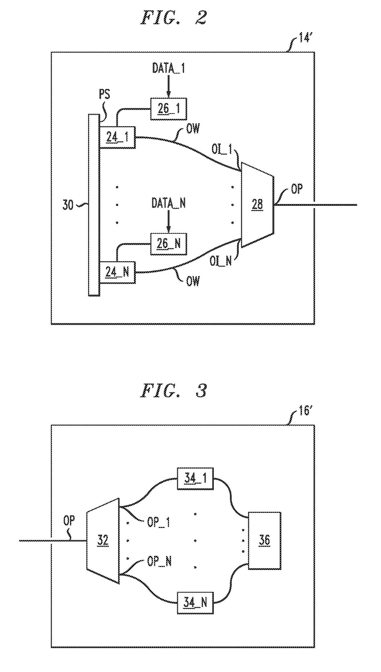
[0051]FIG. 3 illustrates an embodiment 16′ of the optical data receiver 16, which is present in one or both of the nodes 18, 20 of FIGS. 1A-1C. The optical data receiver 16′ includes an all-optical spatial mode multiplexer 32; N light intensity detectors 34_1 . . . 34_N; and an electronic data processor 36 with N electrical inputs.

[0052]The all-optical spatial mode multiplexer 32 is connected to operate in reverse as an all-optical mode demultiplexer in the optical data receiver 16′. In particular, the single optical port of the all-optical spatial mode multiplexer 32 is the input optical port OP of the optical data receiver 16′. The array of N optical ports OP_1, . . . , OP_N of the all-optical spatial mode multiplexer 32 are connected to output light received from the input optical port OP of the optical data receiver 16′.

[0053]Each light intensity detector 34_1-34_N is optically connected to receive light from a corresponding one of the array of N optical ports of the all-optical...


PUM


Abstract

An optical data transmitter includes vertical cavity surface-emitting lasers and an all-optical spatial mode multiplexer. Each vertical cavity surface-emitting laser is configured to output a data modulated optical carrier at a center wavelength of less than one micrometer. The all-optical spatial mode multiplexer has an optical output and optical inputs. Each vertical cavity surface-emitting lasers is optically connected to one or more of the optical inputs of the all-optical spatial mode multiplexer. The all-optical spatial mode multiplexer is configured to cause at least two of the vertical cavity surface-emitting lasers to excite linearly independent combinations of one or more optical spatial propagating modes of an optical fiber in response to the optical output being coupled to a near end of the optical fiber.

Description

BACKGROUND[0001]Technical Field[0002]The inventions relate to apparatus and methods for optical fiber communications.[0003]Related Art[0004]This section introduces aspects that may be helpful to facilitating a better understanding of the inventions. Accordingly, the statements of this section are to be read in this light and are not to be understood as admissions about what is in the prior art or what is not in the prior art.[0005]The technique of optical spatial division multiplexing involves transmitted data over an optical fiber line with a plurality of optical spatial propagating modes. In optical spatial division multiplexing, at least, two of the optical spatial propagating modes have different phase and / or intensity profiles lateral to the propagation direction and may carry different data.[0006]Presently, interest has been generated in optical spatial division multiplexing systems for optical transport networks. Optical transport networks usually operate in optical communica...

Claims


Application Information

Patent Timeline
Patent Type & Authority Patents(United States)
IPC IPC(8): H04J14/04H04B10/2581H04J14/00H04J14/06H04J14/02
CPCH04J14/04H04B10/2581H04J14/06H04J14/00H04J14/02H04B10/503
Inventor CHOWDHURY, AREFRYF, ROLAND
Owner NOKIA OF AMERICA CORP
Why Eureka
Try Eureka