
Transformer noise suppression method

a transformer and noise suppression technology, applied in frequency response correction, instruments, computing models, etc., can solve the problems of slow convergence speed, nonlinear noise, slow noise attenuation of part of noise, etc., to reduce the noise of transformers and other noise sources, reduce noise quickly, and reduce noise. high cost

Active Publication Date: 2018-09-25
JIANGSU ELECTRIC POWER CO +2
View PDF10 Cites 0 Cited by
  • Summary
  • Abstract
  • Description
  • Claims
  • Application Information

AI Technical Summary

Benefits of technology

[0006]The object of the present invention is to disclose a transformer noise suppressing method which can effectively reduce noise.
[0013]Compared with the current technology, the invention can effectively reduce the noise of the transformer and other noise sources in the substation by setting up a complete set of single channel transformer noise reduction system. The invention can rapidly suppress the noise in a certain range of the noise source such as the transformer by means of BP neural network and solve the problems of high cost, poor effect and poor portability of the traditional noise reduction method.

Problems solved by technology

Research shows that the substation noise is mainly the noise of large power transformer, and the power transformer noise comes from the transformer body and cooling system.
Transformer body noise mainly from the core vibration caused by the magnetostriction of silicon steel sheet and the electromagnetic force generated by the current flowing through the winding.
Transformer cooling system noise is mainly due to the fan and oil pump running vibration.
This part of noise attenuation is fast.
Transformer low frequency noise is the main cause of environmental pollution, control of this part of the noise is necessary.
Although the traditional F-XLMS filter algorithm can suppress all the frequency components of noise, but it cannot deal with time-varying, nonlinear noise.
Traditional BP neural network inherent convergence speed is slow and is easy to fall into the local minimum, so that the effect of noise control is not ideal.

Method used


Image

  • Transformer noise suppression method
  • Transformer noise suppression method
  • Transformer noise suppression method

Examples


Embodiment Construction

[0020]The technical solution of the present invention will be described in further detail with reference to the accompanying drawings.

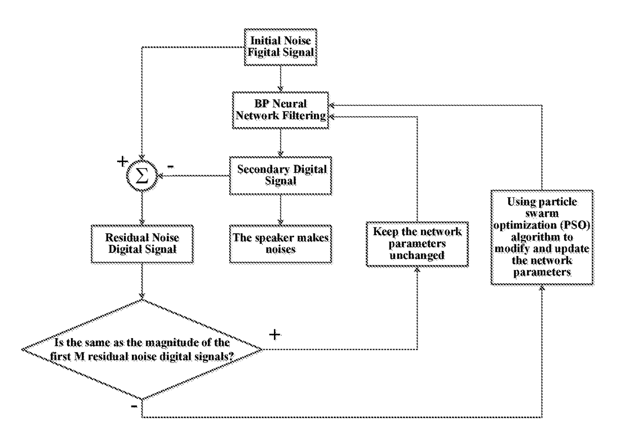
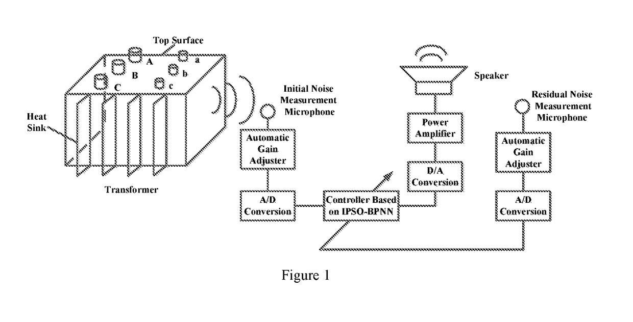
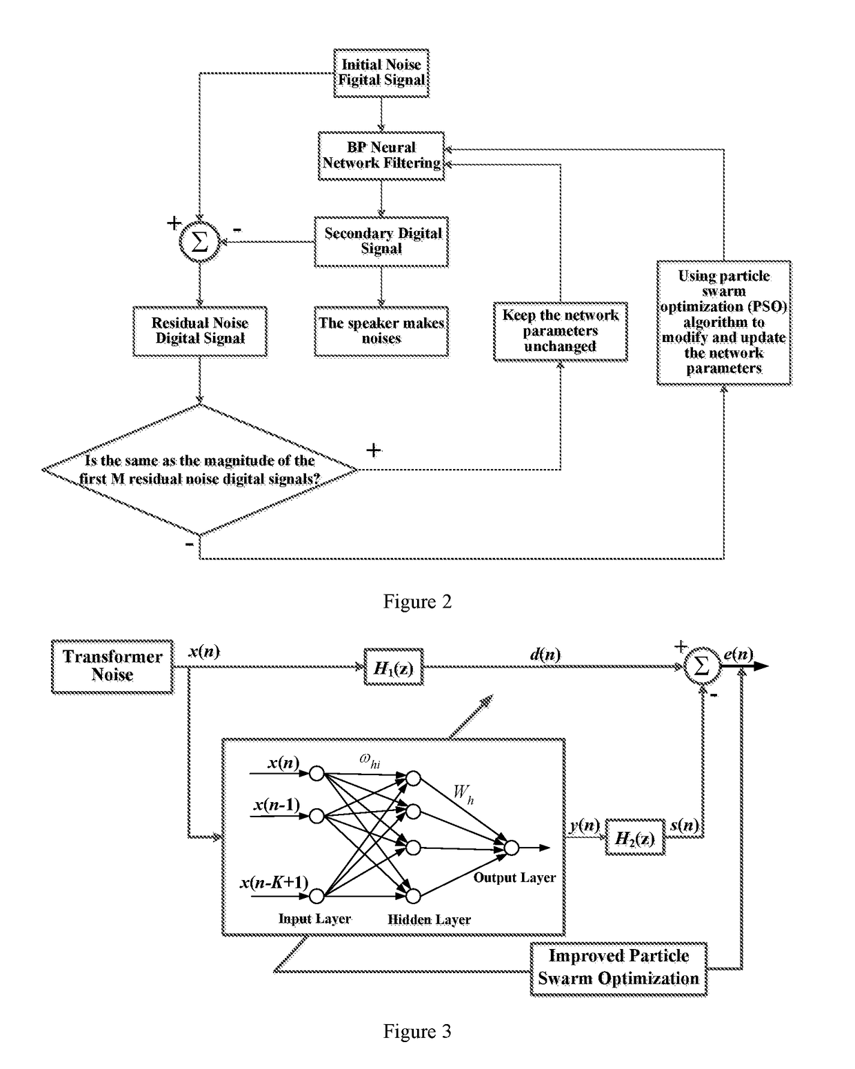
[0021]The present embodiment is a transformer noise suppression method based on an improved particle BP neural network. It will not only effectively suppress noise, but also further to overcome the drawback that BP neural network convergence rate is slow and easy to fall into the local minimum. As shown in FIG. 1, main components of the system include: the controller which contains TMS320VC5509DSP smart chip, 2 PCM6110 microphones as initial noise measuring microphone and residual noise measuring microphone respectively, Swans S6.5 low frequency speaker. The initial noise measurement microphone and the residual noise measurement microphone are connected with the corresponding input port of DSP chip via the automatic gain adjustment module of the sound processing chip and A / D converter module. The output port of the DSP chip is connected with the speak...


PUM

PropertyMeasurementUnit
frequencyaaaaaaaaaa
frequencyaaaaaaaaaa
distanceaaaaaaaaaa

Abstract

The noise suppression method of individual active noise reduction system comprises the steps that: (1) initial noise digital signals are received and converted to serve as input signals of a BP neural network; (2) the input signals are processed to generate secondary digital signals; (3) the secondary digital signals are output to a loudspeaker and secondary noise is generated; (4) remained noise digital signals obtained by overlapping the initial noise and the secondary noise are received; whether remained noise digital signals is continuously constant for the set times is judged; if yes, the secondary digital signals are kept outputting; (5) if not, BP neural network parameters are optimized and adjusted with the amplitude of the remained noise digital signals being minimum as the optimality principle; remained noise digital signals of previous step are served as new input signals and the step (2) is executed again.

Description

CROSS REFERENCE TO RELATED APPLICATION[0001]This application is a National Phase application of, and claims priority to, PCT Application No. PCT / CN2015 / 070735, filed on Jan. 15, 2015 entitled “A TRANSFORMER NOISE SUPPRESSION METHOD,” which claims priority to Chinese Application No. 201410189040.5, filed on May 6, 2014. Both the PCT Application and Chinese Application are incorporated herein by reference in their entireties.TECHNICAL FIELD[0002]The invention relates to a method for suppressing transformer noise, in particular to a transformer noise suppression method based on improved particle BP neural network, and belongs to the technical field of power supply.TECHNIQUE BACKGROUND[0003]Research shows that the substation noise is mainly the noise of large power transformer, and the power transformer noise comes from the transformer body and cooling system.[0004]Transformer body noise mainly from the core vibration caused by the magnetostriction of silicon steel sheet and the electro...

Claims


Application Information

Patent Timeline
Patent Type & Authority Patents(United States)
IPC IPC(8): G10K11/178H01F27/33G06F17/11G06N3/04H04R3/04G06N5/04H04R3/00G06N3/02G10L21/0232G06N3/08
CPCG10L21/0232G06N3/02G06N3/04G06N3/084G06N5/04G10K11/1785G10K11/17881H01F27/33H04R3/005H04R3/04G06F17/11H04R2410/05G10K2210/125G10K2210/3026G10K2210/3027G10K2210/3038G06N3/006G06N3/08G10K11/17825G10K11/17855G10K11/17854G06N7/01
Inventor JIANG, NINGMA, HONGZHONGLI, KAIXU, HONGHUAWANG, CHUNNINGCHEN, BINGBINGJIANG, HONGYU
Owner JIANGSU ELECTRIC POWER CO
Learn More