Auto catch apparatus and method of use in making chemical mechanical polishing pads

a technology of automatic catch and polishing pad, which is applied in the direction of grinding device, manufacturing tool, other domestic articles, etc., can solve the problems of exposing the user to splash and vapor hazards, reducing yield and raw material waste, and avoiding defects or outright loss of the entire cake

Active Publication Date: 2018-10-02
ROHM & HAAS ELECTRONICS MATERIALS CMP HLDG INC
View PDF6 Cites 0 Cited by
  • Summary
  • Abstract
  • Description
  • Claims
  • Application Information

AI Technical Summary

Benefits of technology

[0002]The manufacture of polishing pads for use in chemical mechanical planarization is known to include the pouring, e.g. by pumping, of a urethane forming mixture into a mold and curing, followed by demolding and cutting the cured polyurethane in a direction parallel to the surface of the mold to form a layer having desired thickness, for example, by skiving, and then by shaping the resulting layer, for example, by grinding, routing or embossing into a polishing pad. Previously, known methods of forming such moldings required the user to manually stop the pouring of the urethane forming mixture after the filling of each mold. This meant that the user to had to insert a small container under the pouring stream of urethane forming mixture quickly while keeping the pour nozzle very close to the mold surface and without making any contact with the material in the mold (the “cake”); then the user had to raise the nozzle and get a larger container, such as a bucket, underneath it to capture the urethane forming mixture as it continued to pour after the filling of the mold until the pouring could be stopped. The manual process caused defects when the operator or the container would make contact with the cake; for example, the action of sliding a small container underneath a stream of fluid material commonly resulted in the deposition of a small amount of material unevenly onto the top of the mold on the opposite side from which the container was inserted by the user, resulting in a “sling defect”. Aside from the skill required, the operation had the user positioned right above the cake while the urethane forming mixture was pouring, thereby exposing the user to splash and vapor hazards. In addition, to save on raw material costs, the pumping of the urethane forming mixture had to be stopped after the filling of each mold, resulting in lower yields and raw material waste.
[0015]11. In accordance with another aspect of the present invention, methods for using the apparatus of the present invention as in any one of items 1 to 10, above, comprise continuously mixing and pouring a curable fluid stream from the (ii) dispenser unit into a mold to form a cake and cutting the curable fluid stream cleanly using the (i) set of plates and close to the top surface of the cake to avoid defects or outright loss of the entire cake.

Problems solved by technology

The manual process caused defects when the operator or the container would make contact with the cake; for example, the action of sliding a small container underneath a stream of fluid material commonly resulted in the deposition of a small amount of material unevenly onto the top of the mold on the opposite side from which the container was inserted by the user, resulting in a “sling defect”.
Aside from the skill required, the operation had the user positioned right above the cake while the urethane forming mixture was pouring, thereby exposing the user to splash and vapor hazards.
In addition, to save on raw material costs, the pumping of the urethane forming mixture had to be stopped after the filling of each mold, resulting in lower yields and raw material waste.
Chengzhong fails to disclose continuous molding methods or any solution to enable continuous pouring into successive molds.

Method used


Image

  • Auto catch apparatus and method of use in making chemical mechanical polishing pads
  • Auto catch apparatus and method of use in making chemical mechanical polishing pads
  • Auto catch apparatus and method of use in making chemical mechanical polishing pads

Examples


Embodiment Construction

[0080]Molding trials were conducted with a continuous process of the present invention using a microsphere polymer filled one component polyurethane mixed and poured into a round cake shaped mold via a vertically disposed dispenser unit. Each of Example 1 (Inventive) and Comparative Example 2 were continued for a total of 5 molds (cakes).

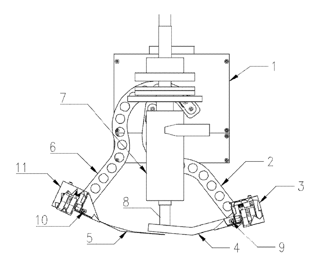
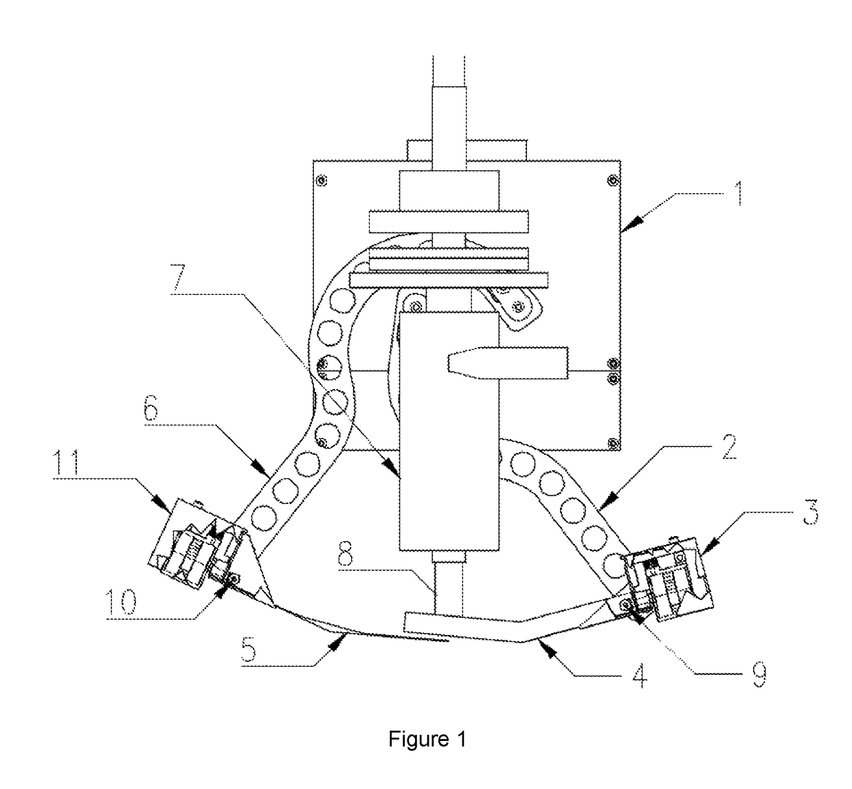
[0081]In Example 1, the apparatus of the present invention as shown in FIG. 1 was used, with a live person inserting a 3.785 L bucket under the dispenser unit to catch the set of two plates, a catch plate and a sling plate, and the microsphere polymer filled polyurethane poured after each mold is full and before pouring into next mold can begin. Also, in Example 1, the apparatus was affixed to an automated Z axis ball screw raising and lowering the dispenser unit and the actuator unit in an out of the molds.

[0082]In Comparative Example 2, the dispenser unit and the actuator unit was moved by a robot with all axes in a fixed position to enable draina...


PUM

PropertyMeasurementUnit
heightaaaaaaaaaa
heightaaaaaaaaaa
densityaaaaaaaaaa

Abstract

The present invention provides an apparatus for use in mixing and dispensing a curable fluid stream (stream) into an open mold to fill the mold to make polishing pads for chemical mechanical planarization of substrates. The apparatus comprises an actuator frame on which is mounted (i) a set of two plates releasably attached to the actuator frame and adapted to cut the stream when the mold is full and to release from the actuator frame after cutting the stream, and (ii) a dispenser unit for continuous pouring of the stream into an open mold, the apparatus adapted to enable removal of the released plates from the actuator during the continuous pouring after the mold is full, e.g. by raising the actuator frame and the (ii) dispenser unit, whereby one can place a container above the mold to catch the plates.

Description

[0001]The present invention relates to an apparatus for use in mixing and dispensing a curable fluid stream into a mold to make polishing pads for chemical mechanical planarization of substrates, the apparatus comprising an actuator frame on which is mounted (i) a set of plates releasably attached to the actuator frame and adapted to cut the curable fluid stream when the mold is full and to release from the actuator frame after cutting the curable fluid stream, and (ii) a dispenser unit for continuous pouring of the curable fluid stream into an open mold and adapted to enable removal of the released plates from the actuator during the continuous pouring and subsequent pouring into a new mold, as well as methods for using the apparatus.[0002]The manufacture of polishing pads for use in chemical mechanical planarization is known to include the pouring, e.g. by pumping, of a urethane forming mixture into a mold and curing, followed by demolding and cutting the cured polyurethane in a d...

Claims


Application Information

Patent Timeline
Patent Type & Authority Patents(United States)
IPC IPC(8): B29C44/34B29C44/60B29C44/02B29C44/40B29K75/00B29K105/04B29L31/00
CPCB29C44/35B29C44/02B29C44/40B29C44/60B29L2031/736B29K2075/00B29K2105/04B29C39/06B29C39/22B29C31/042B29C39/24B29B7/7404B29B7/582B29B7/588B24D18/0009H01L21/304H01L21/30625B29B7/7471B29B7/7414B29B7/7428
Inventor CANTRELL, BRIAN T.
Owner ROHM & HAAS ELECTRONICS MATERIALS CMP HLDG INC
Why Eureka
Try Eureka