
Compact mass spectrometer

a mass spectrometer and compact technology, applied in the direction of ion source/gun, ion source/gun, electric discharge tube, etc., can solve the problems of limiting the sensitivity of instruments, large vacuum pump, and difficulty in replacing a conventional sized orifice with a smaller orifice, so as to achieve improve the effect of pressure-length and small spread of ion energies

Active Publication Date: 2018-10-02
MICROMASS UK LTD
View PDF30 Cites 0 Cited by
  • Summary
  • Abstract
  • Description
  • Claims
  • Application Information

AI Technical Summary

Benefits of technology

This configuration enables a compact, sensitive, and cost-effective mass spectrometer with improved ion transmission and detection capabilities, comparable to full-size instruments, while reducing the size and weight by using smaller pumps and fewer components.

Problems solved by technology

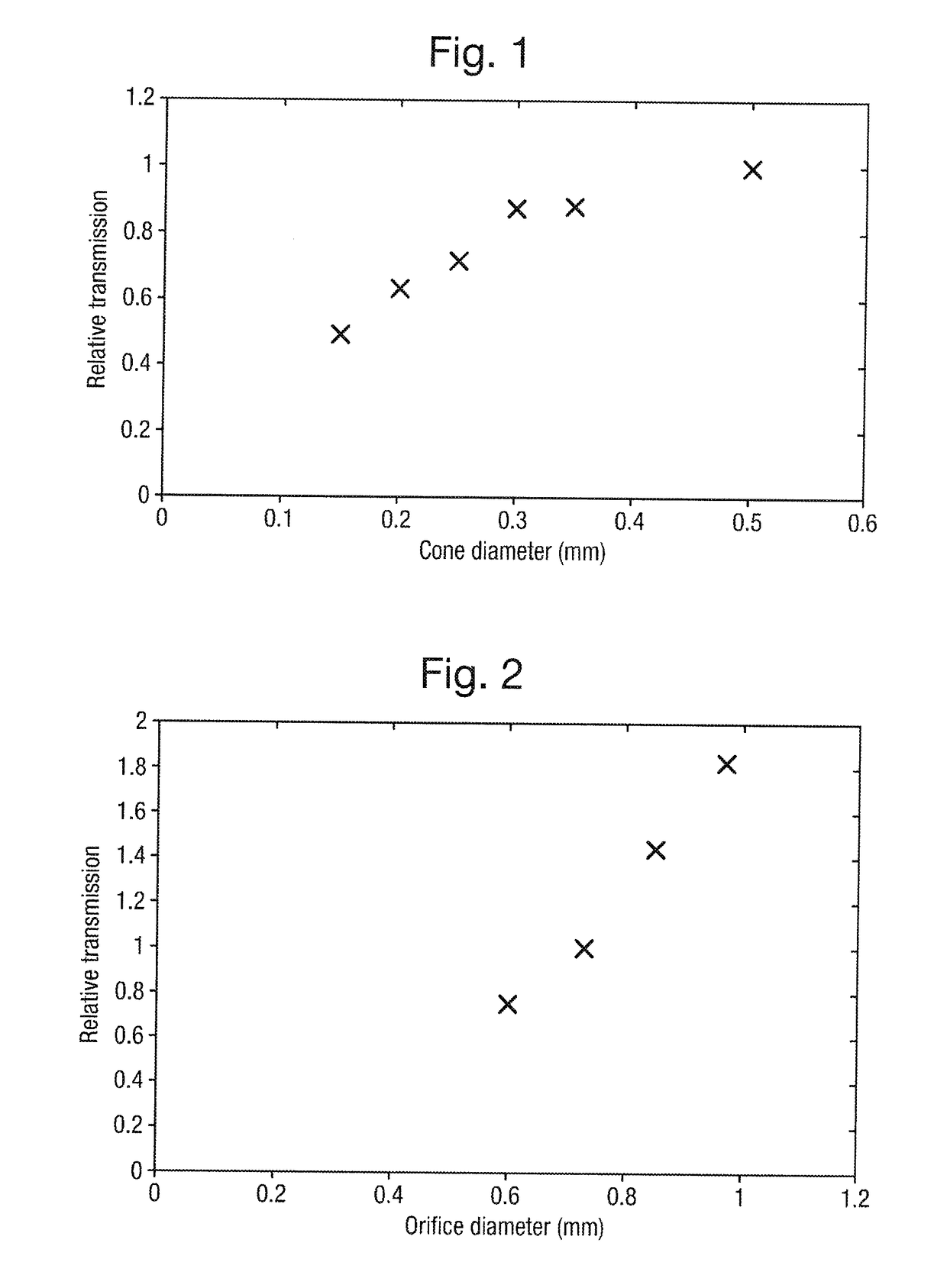
A single orifice between the ion source at atmospheric pressure and the mass analyser is the most direct method but is generally impractical since either the atmospheric pressure orifice needs to be made so small that the number of ions transmitted into the vacuum chamber will be very low (thereby severely restricting the sensitivity of the instrument) or alternatively the mass spectrometer requires an impractically large vacuum pump.
However, replacing a conventional sized orifice with a smaller orifice is problematic since the smaller orifice will have a detrimental effect upon the sensitivity of the instrument.
Reducing the sensitivity of the instrument will limit the usefulness of the miniature mass spectrometer and make it less commercially viable.

Method used


Image

  • Compact mass spectrometer
  • Compact mass spectrometer
  • Compact mass spectrometer

Examples


Embodiment Construction

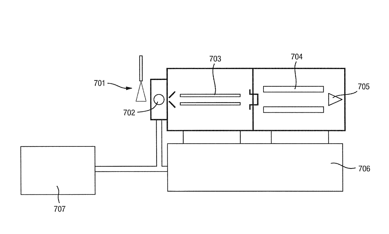
[0169]A preferred embodiment of the present invention will now be described. The preferred embodiment relates to a compact or miniature mass spectrometer which preferably maintains a level of sensitivity similar to current commercial full size mass spectrometers but which is substantially smaller (3 c.f. >0.15 m3 for a conventional full size instrument), lighter (70 kg) and less expensive.

[0170]The preferred miniature mass spectrometer utilises a small backing vacuum pump and a small turbomolecular vacuum pump with considerably lower pumping speeds (300 L / s for a full size turbomolecular vacuum pump and 3 / h c.f. >30 m3 / h for the backing vacuum pump) than a conventional full size mass spectrometer and which consequently consumes considerably less electricity and generates considerably less heat and noise than a conventional full size mass spectrometer.

[0171]The preferred mass spectrometer is preferably used for real time on-line analysis of samples separated using high pressure or ul...


PUM


Abstract

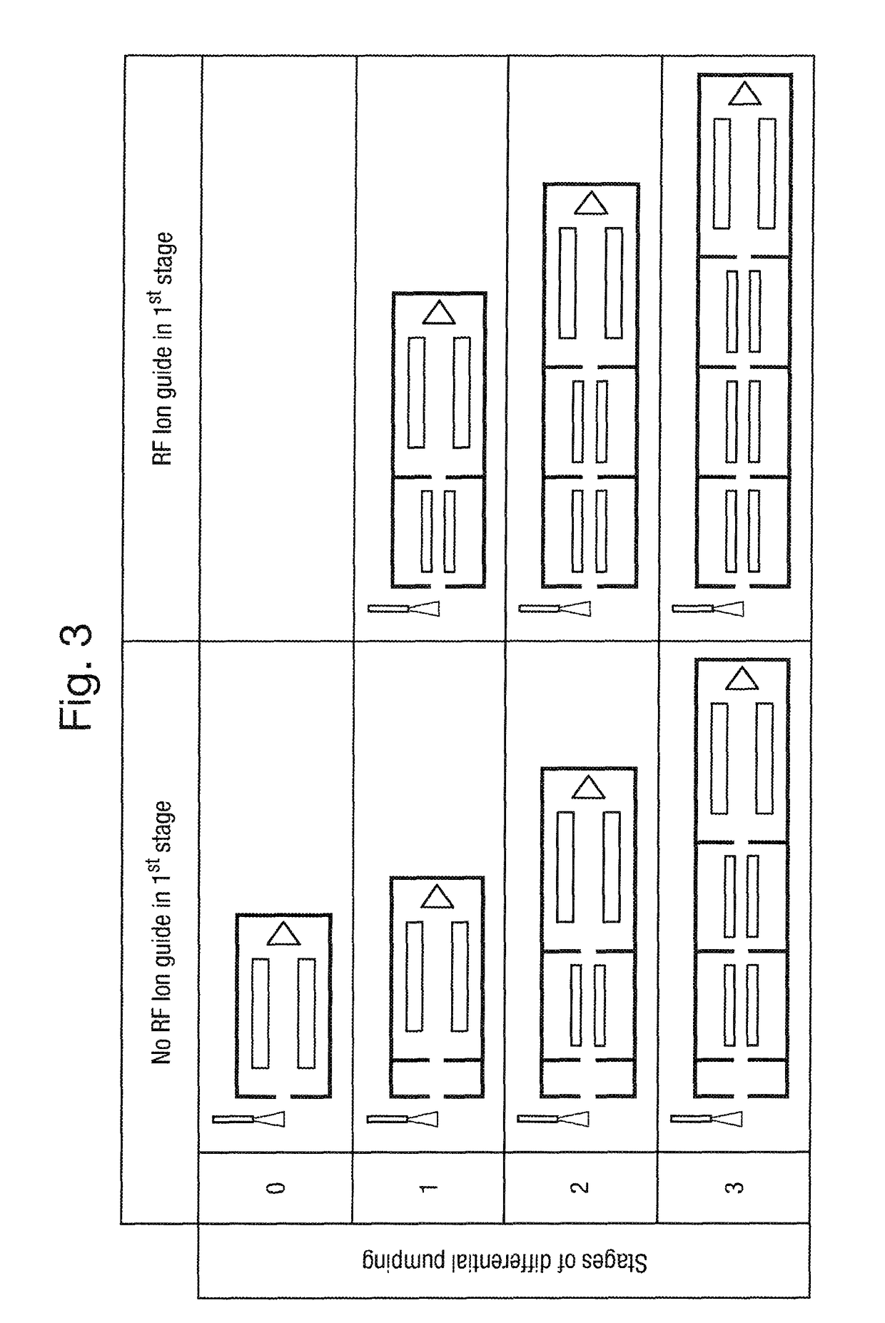
A miniature mass spectrometer is disclosed comprising an atmospheric pressure ionisation source, a first vacuum chamber having an atmospheric pressure sampling orifice or capillary, a second vacuum chamber located downstream of the first vacuum chamber and a third vacuum chamber located downstream of the second vacuum chamber. An ion detector is located in the third vacuum chamber. A first RF ion guide is located within the first vacuum chamber and a second RF ion guide is located within the second vacuum chamber. The ion path length from the atmospheric pressure sampling orifice or capillary to an ion detecting surface of the ion detector is ≤400 mm. The product of the pressure P1 in the vicinity of the first RF ion guide and the length L1 of the first RF ion guide is in the range 10-100 mbar-cm and the product of the pressure P2 in the vicinity of the second RF ion guide and the length L2 of the second RF ion guide is in the range 0.05-0.3 mbar-cm.

Description

CROSS-REFERENCE TO RELATED APPLICATION[0001]This application is the National Stage of International Application No. PCT / GB2014 / 051640, filed 29 May 2014 which claims priority from and the benefit of United Kingdom patent application No. 1309763.9 filed on 31 May 2013, United Kingdom patent application No. 1309762.1 filed on 31 May 2013 and European patent application No. 13170146.8 filed on 31 May 2013. The entire contents of these applications are incorporated herein by reference.BACKGROUND OF THE PRESENT INVENTION[0002]The present invention relates to a mass spectrometer and a method of mass spectrometry. The preferred embodiment relates to a compact or miniature mass spectrometer in conjunction with an Atmospheric Pressure Ionisation (“API”) ion source.[0003]Conventional mass analysers are normally unable to operate at or near atmospheric pressure and so are located within a vacuum chamber that is evacuated to a low pressure. Most commercial mass analysers operate at a vacuum lev...

Claims


Application Information

Patent Timeline
Patent Type & Authority Patents(United States)
IPC IPC(8): H01J49/00H01J49/06H01J49/24H01J49/10
CPCH01J49/0013H01J49/24H01J49/10H01J49/062
Inventor GORDON, DAVIDKENNY, DANIEL JAMES
Owner MICROMASS UK LTD
Learn More