Multirotor drone with variable center of lift

a multi-rotor drone and lift technology, which is applied in the direction of unmanned aerial vehicles, vertical landing/take-off aircraft, remote controlled aircraft, etc., can solve the problems of maneuverability and stability, and the speed at which an engine or electric motor operates affect the flight time of the drone, so as to enhance maneuverability, enhance stability, and extend flight time

Inactive Publication Date: 2018-10-09
ALNAFISAH KHALID HAMAD MUTLEB
View PDF11 Cites 5 Cited by
  • Summary
  • Abstract
  • Description
  • Claims
  • Application Information

AI Technical Summary

Benefits of technology

[0008]Multirotor drone roll and pitch is controlled, for example, by having half the rotors turn one direction while the other half rotate the opposite direction to cancel out gyroscopic effects. Yaw is produced by increasing the relative rotational speed of a diagonal set of rotors with respect to the opposite pair of rotors, while roll and pitch are produced by increasing the relative rotational speed of adjacent rotors on one side of the drone. Increasing relative speed of rotors can also include reducing the rotational speed of other rotors, or some combination of rotational speed adjustment among a plurality of rotors. In general, the greater the angle a drone tilts toward the direction of travel, the faster it will fly.
[0011]Further, the speed at which an engine or electric motor operates affects the flight time of the drone. For either propulsion type there is generally some finite amount of energy that is carried on-board. The ability to operate an engine or motor at or near its most efficient speed can extend flight time. Adjusting the length of one or more of the rotor booms, and therefore the torque created by the rotors' lift about the drone, in combination with altering motor and rotor speeds can enhance stability, maneuverability, and energy efficiency and flight time.

Problems solved by technology

As drone use proliferates and the range of applications expand, a number of shortcomings in the state of the art have appeared, namely limited flight time between refueling or recharging, and dynamic maneuverability and stability, an acute problem for smaller drones operating in windy conditions.
Further, the speed at which an engine or electric motor operates affects the flight time of the drone.

Method used


Image

  • Multirotor drone with variable center of lift
  • Multirotor drone with variable center of lift
  • Multirotor drone with variable center of lift

Examples


Embodiment Construction

[0023]In the drawings, like reference numerals designate identical or corresponding parts throughout the several views. Further, as used herein, the words “a”, “an” and the like generally carry a meaning of “one or more”, unless stated otherwise. The drawings are generally drawn to scale unless specified otherwise or illustrating schematic structures or flowcharts.

[0024]Referring now to the drawings, wherein like reference numerals designate identical or corresponding parts throughout the several views.

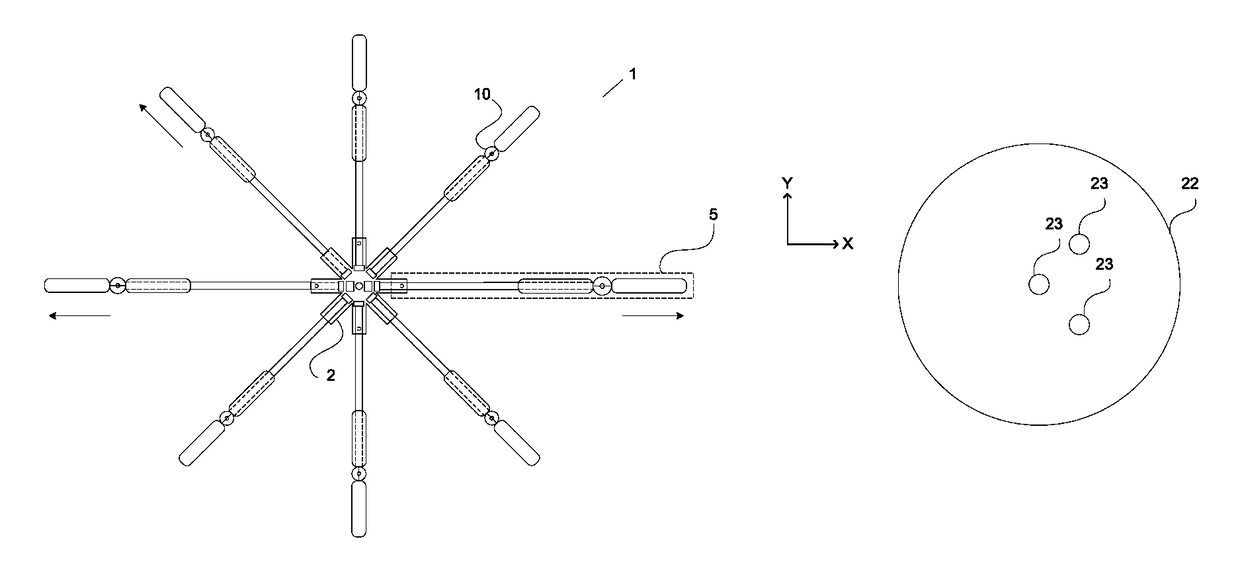
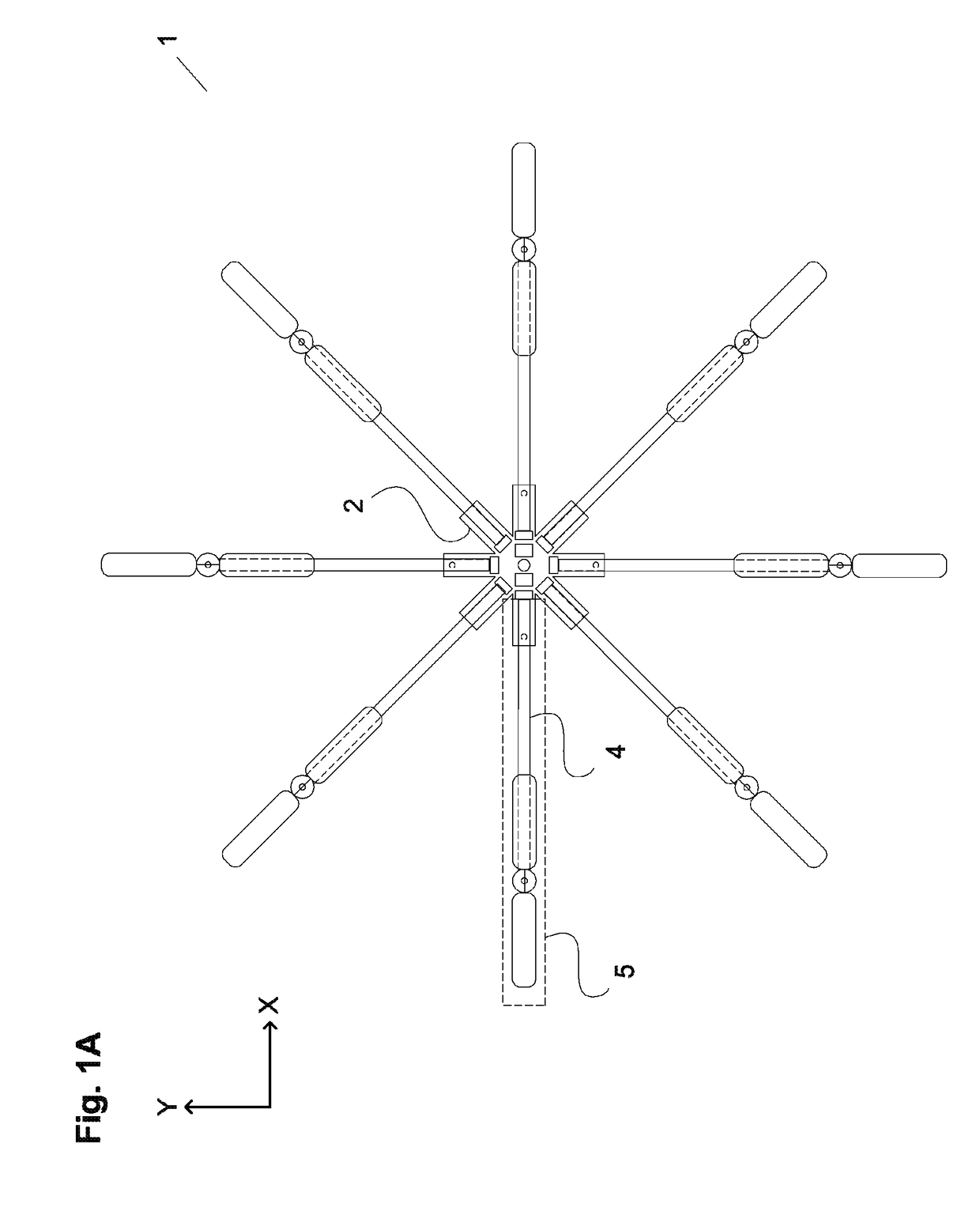
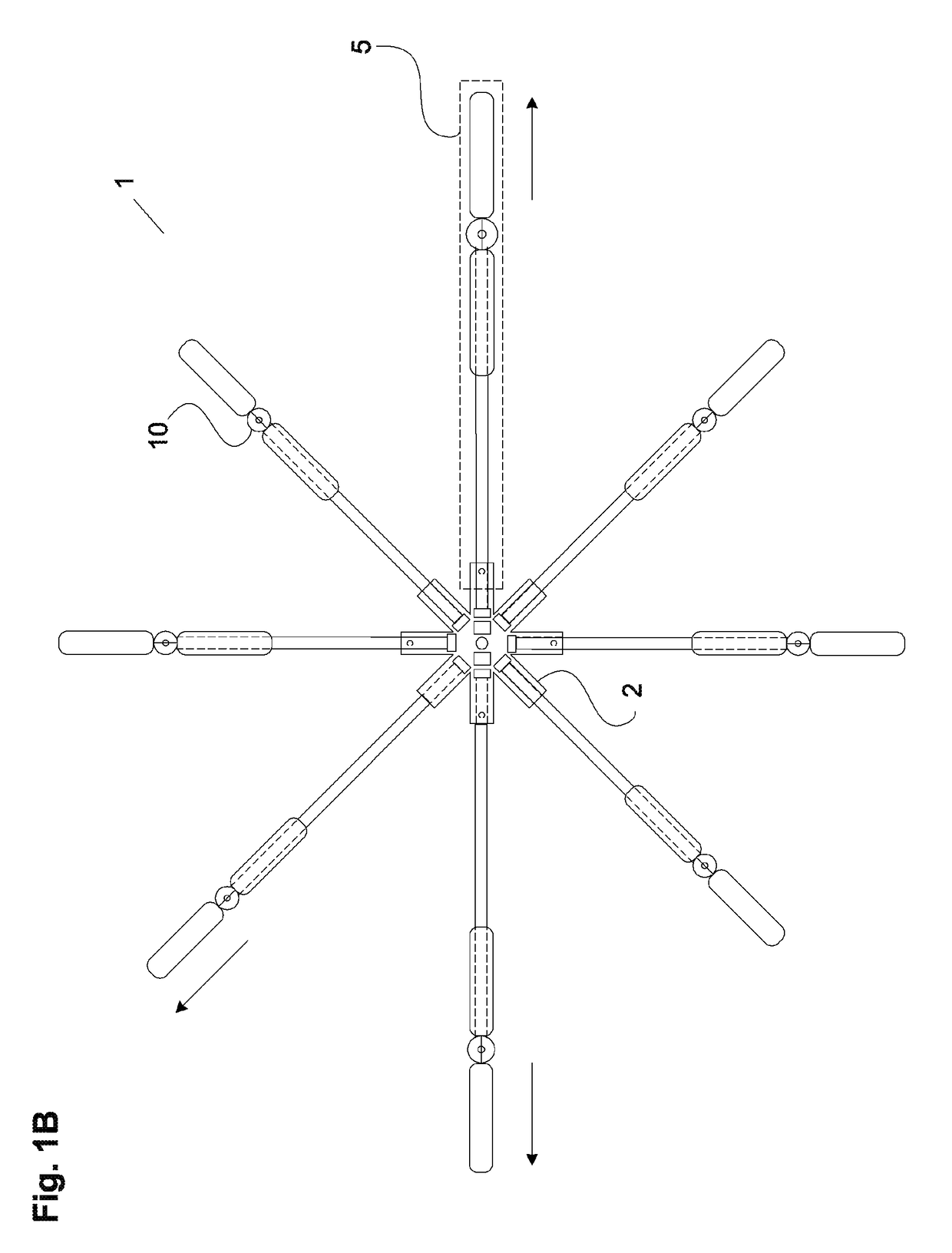
[0025]FIG. 1A is a plan view of an embodiment of a multirotor drone 1, a multirotor drone capable of vertical takeoff and landing (VTOL), and externally controlled by wireless communication or by autonomous function, and having multiple instances of a rotor assembly 5 arranged about the center of a main frame 2.

[0026]The position of each of the rotor assemblies 5 is adjustable along a horizontal axis in the X-Y plane relative to the main frame 2, shown with each in the fully retracted...


PUM


Abstract

A system and method for efficiently maneuvering a multirotor drone having a control system, an electrical power source, a plurality of rotor assemblies each having a rotor boom, a rotor mast, at least one rotor blade, a rotor assembly adjustment apparatus, a plurality of electric motors, wherein each electric motor is connected to a rotor boom positioned in a substantially horizontal direction and drives a rotor mast positioned in a substantially vertical direction and connected to at least one rotor blade, with the position of said rotor boom automatically adjustable in a substantially horizontal direction by the adjustment apparatus and the control system.

Description

GRANT OF NON-EXCLUSIVE RIGHT[0001]This application was prepared with financial support from the Saudi Arabian Cultural Mission, and in consideration therefore the present inventor(s) has granted The Kingdom of Saudi Arabia a non-exclusive right to practice the present invention.BACKGROUND[0002]Field of the Disclosure[0003]The present disclosure is directed toward a multirotor drone with a variable center of lift and variable center of mass for dynamic stability over a range of operating conditions.[0004]Description of the Related Art[0005]Autonomous or remotely controlled multirotor drone aircraft with vertical takeoff and landing (VTOL) abilities have become more widely available. These craft are available in various sizes and have many uses including military and surveillance applications, aerial photography and videography, mapping, and package delivery. They take off and fly much like helicopters, though generally without the aid of a tail rotor.[0006]As drone use proliferates a...

Claims


Application Information

Patent Timeline
Patent Type & Authority Patents(United States)
IPC IPC(8): B64C29/00B64C39/02
CPCB64C39/024B64C2201/128B64C2201/042B64C2201/027B64U10/13B64U50/19B64U2101/60
Inventor ALNAFISAH, KHALID HAMAD MUTLEB
Owner ALNAFISAH KHALID HAMAD MUTLEB
Why Eureka
Try Eureka