
Machine learning apparatus and method for learning arrangement position of magnet in rotor and rotor design apparatus including machine learning apparatus

a technology of arrangement position and machine learning, which is applied in the direction of magnetic circuit rotating parts, manufacturing stator/rotor bodies, and magnetic circuit shape/form/construction. it can solve the problems of increasing cost, time required for adjustment, and deteriorating smooth feed of assembled rotors. it is easy to determine the optimal arrangement position of magnets

Active Publication Date: 2018-10-16
FANUC LTD
View PDF24 Cites 1 Cited by
  • Summary
  • Abstract
  • Description
  • Claims
  • Application Information

AI Technical Summary

Benefits of technology

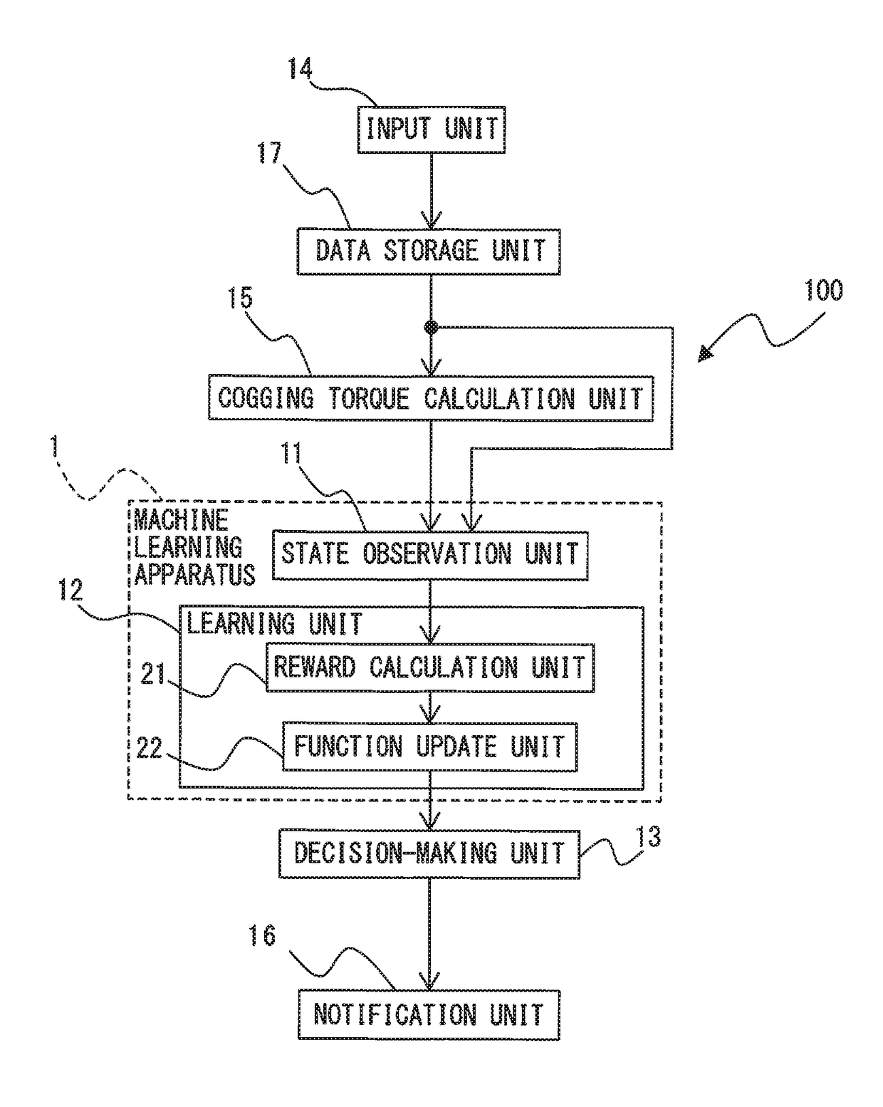
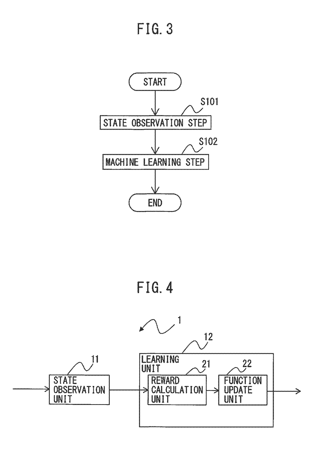
The invention provides a machine learning system and method to easily determine the best positions for arranging magnets on a motor rotor. The system calculates the reward value of each arrangement position based on the magnitude of cogging torque, which is the torque generated when the magnets are placed in a certain position on the motor rotor. By increasing the reward for arrangements that result in smaller cogging torque, and reducing the reward for arrangements that result in larger cogging torque, the system can learn which positions on the rotor are more efficient for arranging magnets. This invention aims to improve the design of motor rotors and reduce cogging torque to improve the performance of motors.

Problems solved by technology

In other words, the smoothness of feed of the rotor assembled (cogging torque) may sometimes deteriorate depending on the arrangement positions of the magnets.
However, there is a problem in that due to the addition of the component, the cost is increased, and time is required for adjustment.
It is unrealistic and virtually difficult to measure the magnetic flux density of each of n pieces of magnets and then perform a simulation analysis of the magnitude of cogging torque for all “n!” arrangement patterns of the magnets, thereby determining the arrangement positions of the magnets for which the magnitude of cogging torque is minimized (the smoothness of feed of the rotor is optimized).

Method used


Image

  • Machine learning apparatus and method for learning arrangement position of magnet in rotor and rotor design apparatus including machine learning apparatus
  • Machine learning apparatus and method for learning arrangement position of magnet in rotor and rotor design apparatus including machine learning apparatus
  • Machine learning apparatus and method for learning arrangement position of magnet in rotor and rotor design apparatus including machine learning apparatus

Examples


Embodiment Construction

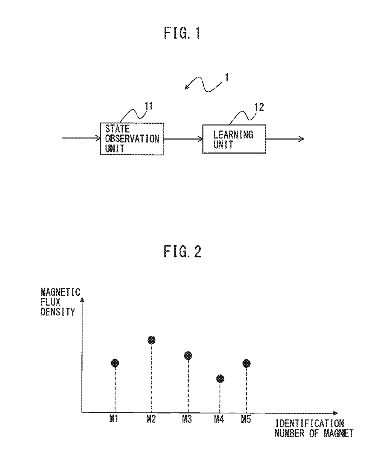
[0031]A machine learning apparatus and method that learn an arrangement position of a magnet on a rotor, and a rotor design apparatus including the machine learning apparatus will be described below with reference to the drawings. However, it should be understood that the present invention is not limited to the drawings or embodiments described below.

[0032]FIG. 1 is a principle block diagram of a machine learning apparatus according to an embodiment. Hereinafter, it is meant that components assigned identical reference numerals in different drawings are those having identical functions.

[0033]A rotor of a synchronous motor is formed such that a plurality of magnets are arranged on a core, and the machine learning apparatus 1 according to the embodiment is configured to learn arrangement positions of the magnets on the core of the rotor of the motor. The present invention is applicable to any motor (synchronous motor) in which magnets are used with the rotor and also to a surface-atta...


PUM


Abstract

A machine learning apparatus, which learns a condition associated with arrangement positions of magnets on a core of a motor rotor, includes: a state observation unit that observes a state variable composed of data relating to arrangement positions of a plurality of the magnets arranged on the core, data relating to a magnitude of cogging torque generated when the plurality of the magnets are arranged at the respective arrangement positions, and data relating to a magnetic flux density of each of the magnets; and a learning unit that learns the condition associated with the arrangement positions of the magnets on the core in accordance with a training data set constituted by the state variable.

Description

RELATED APPLICATIONS[0001]The present application claims priority to Japanese Patent Application Number 2015-193647 filed Sep. 30, 2015, the disclosure of which is hereby incorporated by reference herein in its entirety.BACKGROUND OF THE INVENTION[0002]1. Field of the Invention[0003]The present invention relates to a machine learning apparatus and method for learning an arrangement position of a magnet in a motor rotor, and a rotor design apparatus including the machine learning apparatus.[0004]2. Description of the Related Art[0005]FIG. 11 is a schematic view explaining assemblage a rotor of a general synchronous motor. For example, as described in Japanese Laid-open Patent Publication No. 2010-233325, a rotor 100 of a synchronous motor is formed such that a plurality of magnets 102 are arranged on a circumferential surface of a core 101.[0006]Since each of the magnets arranged on the core forming the rotor has a variation in magnetic flux density, cogging torque varies depending o...

Claims


Application Information

Patent Timeline
Patent Type & Authority Patents(United States)
IPC IPC(8): H02K15/03H02K1/27
CPCH02K1/278H02K15/03G06N3/08G06F30/17G06F30/20
Inventor MURAKAMI, YOSHINORI
Owner FANUC LTD
Learn More