Power module, power converter and manufacturing method of power module

a manufacturing method and power converter technology, applied in the field of power modules, can solve the problems of high switch loss, unavoidable use of additional materials by semiconductor devices, and energy consumption of power converters mainly composed of on-state loss and switch loss, and achieve the effect of increasing space availability, saving the cost of additionally a dbc ceramic substrate, and increasing space availability

Active Publication Date: 2018-10-16
DELTA ELECTRONICS (SHANGHAI) CO LTD
View PDF38 Cites 4 Cited by
  • Summary
  • Abstract
  • Description
  • Claims
  • Application Information

AI Technical Summary

Benefits of technology

[0018]To solve the above problems, the present disclosure provides a power module with higher space availability, in which the power module is formed by disposing planar power devices directly on a heat-dissipating substrate, thereby not only effectively increasing the space availability but also saving the cost of additionally a DBC ceramic substrate and also increasing the heat dissipation of the power module such that the high power density or high efficiency of a power converter can be achieved, and the electric energy conversion efficiency of the power converter can be effectively enhanced.

Problems solved by technology

The energy consumption of the power converter is mainly composed of an on-state loss and a switch loss, especially the switch loss of an active device.
If the magnetic element has a small size, a high frequency is usually needed to decrease the magnetic flux density of the magnetic element in order to achieve reliable work, thus inducing a high switch loss.
However, the use of the semiconductor device tends to unavoidably need to use additional materials, such as a packaging material for protecting the semiconductor device, a heat sink for heat dissipating, a fixture for fixing the semiconductor device, and the like.
As the ratio of these materials inside the power converter gets greater, the internal space availability of the power converter gets worse.
The package space availability of the semiconductor device becomes a bottleneck.
However, because all of the power devices have to be mounted on the DBC ceramic substrate, the DBC ceramic substrate with a larger area is required.
However, the DBC ceramic substrate is relatively expensive, thus increasing the cost of the entire package module.
However, the heat conducive property of aluminum oxide is still worse than that of metal (e.g., the coefficient of heat conductivity of copper is equal to about 400 W / m·K), so that the transversal heat diffusion ability of the DBC ceramic substrate is not good enough, and the poor thermal uniformity thereof tends to occur.
Because of high stress withstand packaging, the corresponding screws holes also need to be designed for stress withstanding, and thus occupies larger actual space.
For example, a screw hole with a 3 mm hole diameter generally occupies an area of which the diameter is greater than 5 mm for meeting the stress withstanding requirements of the power module, thus lowering the space availability of the power module.
Although the space availability of the power module can be enhanced by disposing the controlling device or driving device on the heat sink through thermal insulating layer, the aforementioned problems of the DBC ceramic substrate still cannot be overcome.
Thus, the metal material (such as copper) in the power module is merely used to provide one single function of electrical or thermal conduction, and its electrically and thermally conductive properties are not utilized simultaneously, thus not fully utilizing the features of the material.
In sum, the conventional power modules still have various problems such as poor heat dissipating performance, material wastage, the difficulty of reliability design, not fully utilized electrical performance, the over design caused by over-emphasis on generality, and poor economic performance, etc.
More particularly, the conventional power modules have insufficient space availability, and their applications in high power density or high efficiency occasions are thus restricted.

Method used


Image

  • Power module, power converter and manufacturing method of power module
  • Power module, power converter and manufacturing method of power module
  • Power module, power converter and manufacturing method of power module

Examples


Embodiment Construction

[0063]Specific embodiments of the present invention are further described in detail below with reference to the accompanying drawings, however, the embodiments described are not intended to limit the present invention and it is not intended for the description of operation to limit the order of implementation. Moreover, any device with equivalent functions that is produced from a structure formed by a recombination of elements shall fall within the scope of the present invention. Additionally, the drawings are only illustrative and are not drawn to actual size.

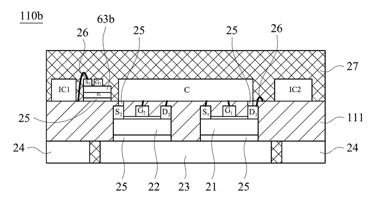
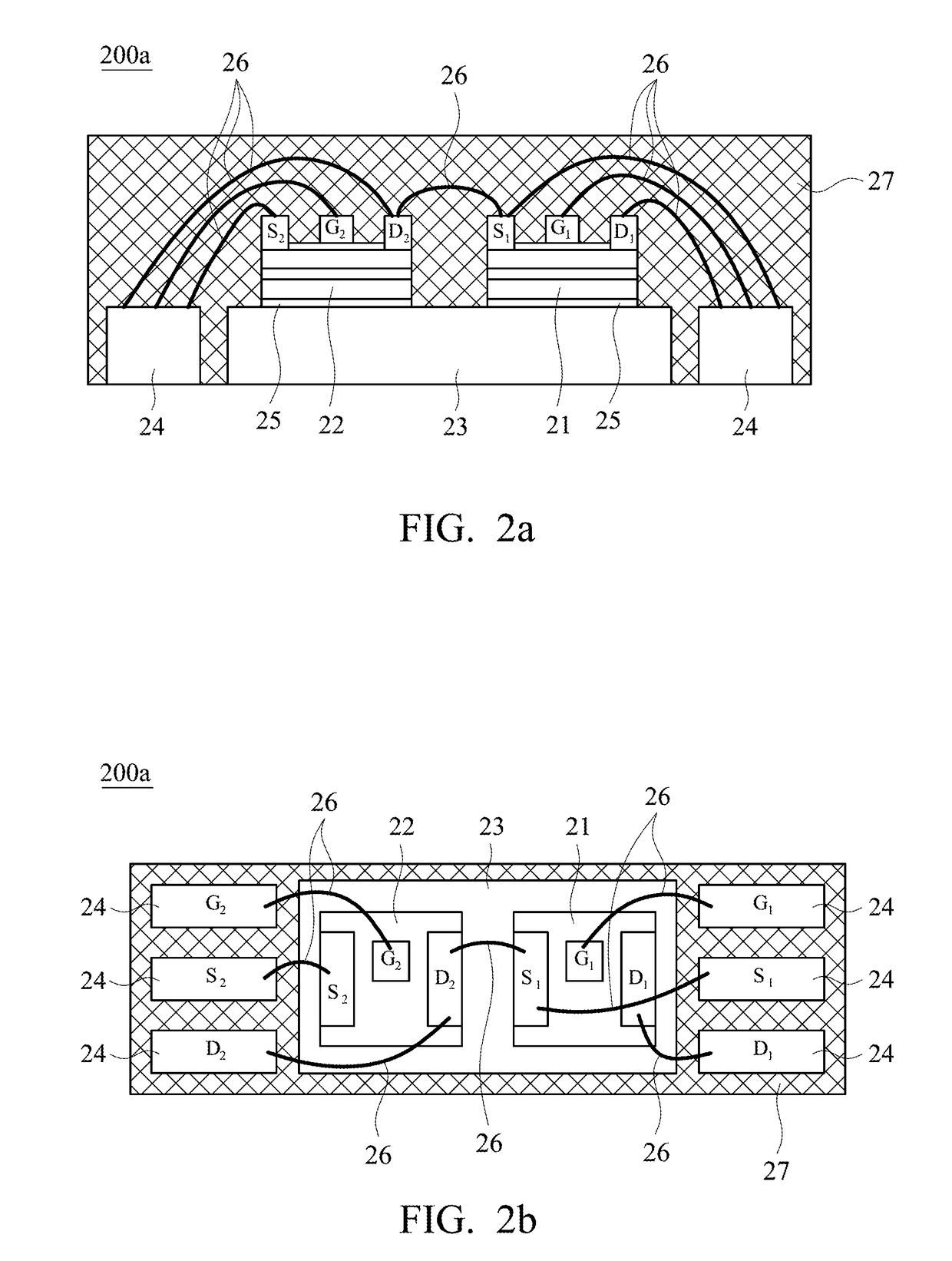
[0064]Referring to FIG. 2a and FIG. 2b, FIG. 2a is a schematic cross-sectional view showing a power module 200a according to an embodiment of the present invention, and FIG. 2b is a schematic top view showing a power module 200a according to FIG. 2a. As shown in FIG. 2a and FIG. 2b, the power module 200a includes at least one first planar power device 21, at least one second planar power device 22, a heat-dissipating substrate...


PUM

PropertyMeasurementUnit
frequencyaaaaaaaaaa
diameteraaaaaaaaaa
diameteraaaaaaaaaa

Abstract

A power module includes a heat-dissipating substrate, a first planar power device and a second planar power device. The first planar power device includes a plurality of electrodes disposed on an upper surface of the first planar power device. The second planar power device includes a plurality of electrodes disposed on an upper surface of the second planar power device. Lower surfaces of the first planar power device and the second planar power device are disposed on the heat-dissipating substrate.

Description

RELATED APPLICATIONS[0001]This application claims priority to China Application Serial Number 201310694495.8 filed Dec. 16, 2013, which is herein incorporated by reference.BACKGROUND[0002]Field of Invention[0003]The present invention relates to a power module. More particularly, the present invention relates to a power module used in a POWER converter.[0004]Description of Related Art[0005]High efficiency and high power density has been the industry's requirements for power converters. High efficiency means less energy consumption, and energy saving helps to reduce carbon and protect environment. High power density stands for small size, lightweight and less space requirement, thereby reducing costs.[0006]The energy consumption of the power converter is mainly composed of an on-state loss and a switch loss, especially the switch loss of an active device. The switch loss is more significantly affected by a working frequency. The power converter, especially the switch power converter, ...

Claims


Application Information

Patent Timeline
Patent Type & Authority Patents(United States)
IPC IPC(8): H05K7/14
CPCH05K7/1432H01L2224/05553Y10T29/4913H01L2924/19105H01L2224/0603H01L2224/32145H01L2224/32245H01L2224/48091H01L2224/48137H01L2224/48247H01L2224/48257H01L2224/73265H01L2924/13055H01L2924/181H01L2924/00014H01L2924/00H01L2924/00012H01L2924/19104H01L2924/13091H05K7/14329H01L2924/00011
Inventor ZENG, JIAN-HONG
Owner DELTA ELECTRONICS (SHANGHAI) CO LTD
Why Eureka
Try Eureka