
Fuel pump

a technology of fuel pump and connection terminal, which is applied in the direction of liquid fuel engines, liquid fuel feeders, machines/engines, etc., can solve the problems of connection terminal, foreign object corroding with foreign object, and water accumulating in the inside of the electric connector, so as to limit the occurrence of corrosion and/or short circuit of the connection terminal

Active Publication Date: 2018-10-23
AISAN IND CO LTD
View PDF35 Cites 0 Cited by
  • Summary
  • Abstract
  • Description
  • Claims
  • Application Information

AI Technical Summary

Benefits of technology

[0006]It is an objective of the present disclosure to provide a fuel pump, which can limit corrosion of connection terminals that receive an electric power form an outside.
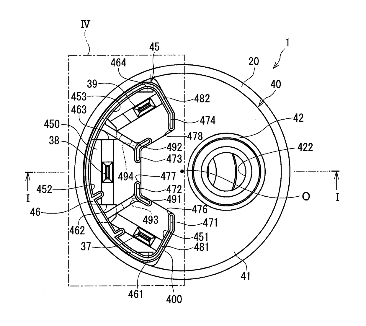
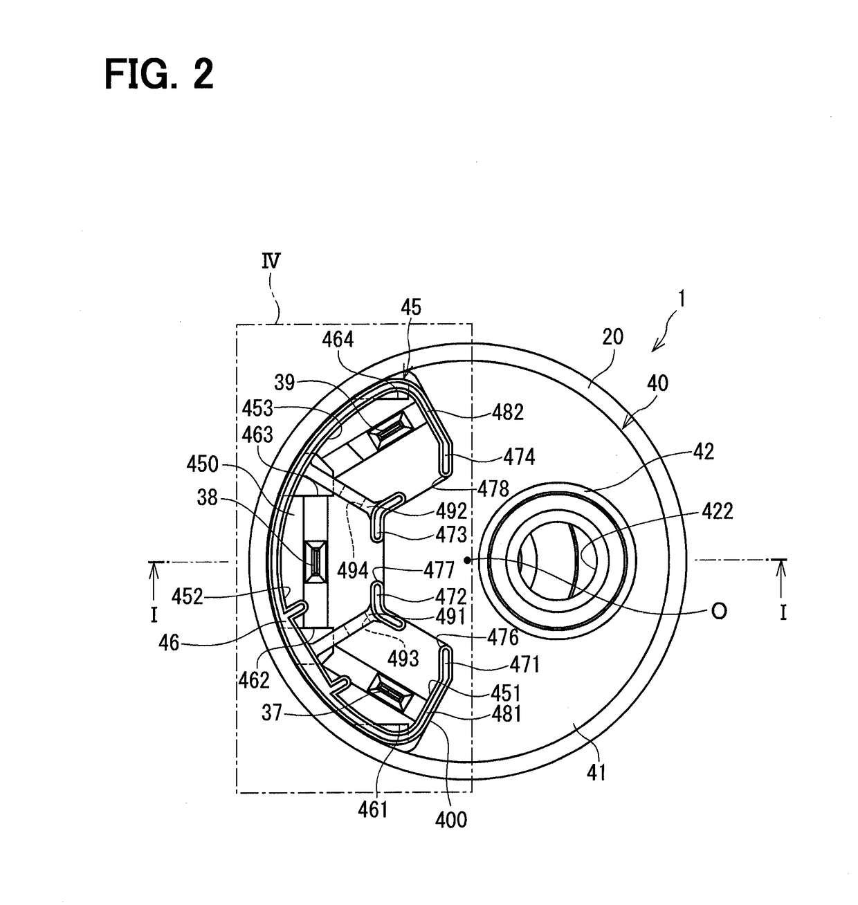
[0008]In the fuel pump of the present disclosure, the plurality of connection terminals, which receive the electric power, is received in the receiving chamber of the electric connector. The electric connector includes the plurality of primary communication holes, each of which communicates between the inside and the outside of the receiving chamber. The plurality of primary communication holes is formed to direct the at least one of the perpendicular directions, each of which is perpendicular to the corresponding one of the opening planes of the outside openings of the plurality of primary communication holes, toward the downside when the central axis of the pump case is tilted relative to the vertical direction. Here, each of the opening planes refers to a corresponding imaginary plane that extends through all of points located along a peripheral edge of the corresponding opening. With the above construction, when the central axis of the pump case is tilted in any of directions, a foreign object, which is accumulated in the receiving chamber of the electric connector, is outputted to the outside of the electric connector through the primary communication hole(s). Therefore, in the fuel pump of the present disclosure, it is possible to limit the occurrence of corrosion and / or short circuit of the connection terminals caused by the foreign object, such as the water.
[0009]A downward side inner wall (bottom wall) of the receiving chamber may decline from an upside to the downside from a location of each of the plurality of connection terminals toward at least one of the plurality of primary communication holes. With this construction, even when the central axis of the pump case is not tilted, the foreign object, such as the water, accumulated in the receiving chamber of the electric connector, can be effectively outputted through the corresponding primary communication hole(s).

Problems solved by technology

Therefore, it could happen that the foreign object, such as the water, which is accumulated in the inside of the electric connector, cannot be outputted to the outside of the electric connector depending on the tilting direction of the fuel pump.
Therefore, connection terminals, which are made of metal and are received in the inside of the electric connector, may possibly corrode with the foreign object, such as the water.

Method used


Image

  • Fuel pump
  • Fuel pump
  • Fuel pump

Examples


Embodiment Construction

[0014]Hereinafter, an embodiment of the present disclosure will be described with reference to the accompanying drawings.

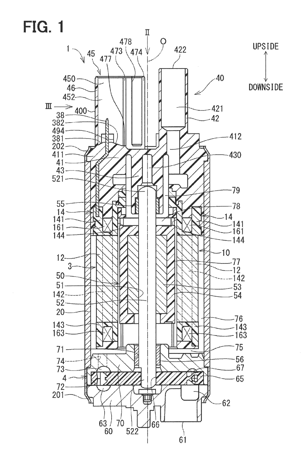
[0015]A fuel pump according to the embodiment of the present disclosure will be described with reference to FIGS. 1 to 4.

[0016]FIG. 1 is a cross-sectional view taken along line I-I in FIG. 2. As shown in FIG. 1, the fuel pump 1 includes a motor arrangement 3, a pump arrangement 4, a housing 20, a pump cover 60, a cover end 40 and an electric connector 45. In the fuel pump 1, the motor arrangement 3 and the pump arrangement 4 are received in a space, which is formed by the housing 20, the pump cover 60 and the cover end 40. The fuel pump 1 draws fuel from a fuel tank (not shown) through a suction port 61, which is indicated at a lower side of FIG. 1, and the fuel pump 1 discharges the drawn fuel toward an internal combustion engine through a discharge port 422, which is indicated at an upper side in FIG. 1. In FIGS. 1 to 4, the upper side will be referred to as “an...


PUM


Abstract

Partitioned chambers of an electric connector, which receive connection terminals electrically connected to windings of a stator, are communicated with an outside of the electric connector through primary communication holes. The primary communication holes are formed to direct at least one of perpendicular directions, each of which is perpendicular to a corresponding one of opening planes of outside openings of the primary communication holes, toward a downside when a central axis of a fuel pump is tilted relative to a vertical direction. In this way, a foreign object, which is accumulated in any of the portioned chambers, can be outputted to the outside through the primary communication hole even when the fuel pump is tilted in any direction.

Description

CROSS REFERENCE TO RELATED APPLICATION[0001]This application is the U.S. national phase of International Application No. PCT / JP2014 / 004531 filed on Sep. 3, 2014 and is based on and incorporates herein by reference Japanese Patent Application No. 2013-191598 filed on Sep. 17, 2013.TECHNICAL FIELD[0002]The present disclosure relates to a fuel pump.BACKGROUND ART[0003]There is known a fuel pump that includes an impeller, which is rotatable in a pump chamber, and a motor, which can drive the impeller to rotate the impeller. The fuel pump pumps fuel of a fuel tank to an internal combustion engine through rotation of the impeller. The fuel pump has an electric connector, which receives an electric power to be supplied to the motor. The Patent Literature 1 recites a fuel pump that has an electric connector, which includes communication holes, and water or the like, which is accumulated in an inside of the electric connector, is outputted to the outside of the electric connector through the...

Claims


Application Information

Patent Timeline
Patent Type & Authority Patents(United States)
IPC IPC(8): F04D13/06F04D3/00F04D29/52F02M37/08F04D5/00
CPCF04D13/06F02M37/08F04D3/00F04D13/0693F04D29/528F04D5/002F05D2260/602F02M2037/082
Inventor OOTAKE, MASAYAHAYAKAWA, TETSUONAGATA, KIYOSHI
Owner AISAN IND CO LTD
Learn More