Optical pen for interferometric measuring machine

an interferometric measuring machine and optical pen technology, applied in the field of optical pen for interferometric measuring machines, can solve the problem of limiting the possibility of relative disturbances differentially affecting the beam, and achieve the effects of reducing the complexity and number of interferometric components, expanding the measurement opportunities of optical pen, and reducing the possibility of disturbances affecting the interferometric function

Active Publication Date: 2018-10-23
QUALITY VISION INT
View PDF34 Cites 1 Cited by
  • Summary
  • Abstract
  • Description
  • Claims
  • Application Information

AI Technical Summary

Benefits of technology

[0005]Among the embodiments, more compact and axially symmetric optical pens are presented that overcome the noted deficiencies and provide for such purposes as expanding measurement opportunities for the optical pens particularly in small working spaces, reducing the complexity and number of interferometric components within the optical pens, and further diminishing possibilities for disturbances affecting the interferometric function of the optical pens.
[0007]In the referenced example, the first focusing optic is traversed once each by the source beam and the measurement beam and is traversed twice by the reference beam (i.e., as the reference beam and returning reference beam). The second focusing optic is traversed twice by the object beam (i.e., as the object beam and the returning object beam). Thus, the same focusing optic that is used for collimating the source beam and focusing the measurement beam is also used for both collimating and focusing the reference beam, eliminating the need for a separate focusing optic to appropriately shape the reference beam.
[0008]The first focusing optic includes an optical axis and a beamsplitter preferably includes an at least partially reflective surface that is inclined at a non-normal angle to the optical axis of the first focusing optic. In this regard, the at least partially reflective surface departs by no more than three degrees from a normal to the optical axis of the first focusing optic so that the reference beam overlaps the source and measurement beams along a substantial portion of their respective paths. The overlap between the reference beam and the source and measurement beams allows for a more compact design. In addition, the first and second focusing optics can share aligned optical axes. All of the beams, including the source, object, reference, and measurement beams preferably propagate along the same or nearly the same axes, which limits the possibility for relative disturbances differentially affecting the beams.
[0010]Particularly when the reference beam propagates in a slightly off-axis direction through the first focusing optic, dispersive or other aberrational effects can be minimized by limiting the reference beam to central or paraxial rays of the source beam. For example, the partially reflective surface can be arranged to reflect central or paraxial rays of the source beam along a reference optical axis that is inclined to a common optical axis of the source and measurement beams without similarly reflecting or otherwise impeding the transmission of more marginal rays of the source beam which form the object beam.
[0012]For extending the optical pathway of the reference beam while limiting its spatial divergence from the volume occupied by the source and measurement beams, an intermediate reflector can be provided for folding the pathway of the reference beam en route to and from the reference reflector. Preferably, the pathway of the reference beam is folded across the common optical axis of the source and measurement beams. As such, the reference reflector can be positioned about the radial periphery of the pen body in a location that is more easily subject to adjustment.

Problems solved by technology

All of the beams, including the source, object, reference, and measurement beams preferably propagate along the same or nearly the same axes, which limits the possibility for relative disturbances differentially affecting the beams.

Method used


Image

  • Optical pen for interferometric measuring machine
  • Optical pen for interferometric measuring machine
  • Optical pen for interferometric measuring machine

Examples


Embodiment Construction

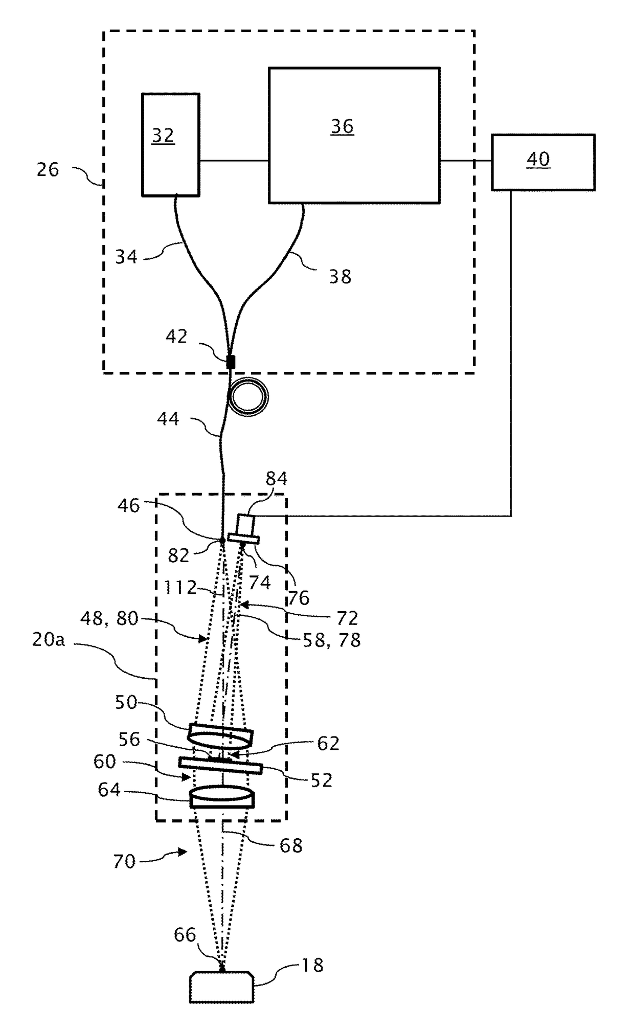
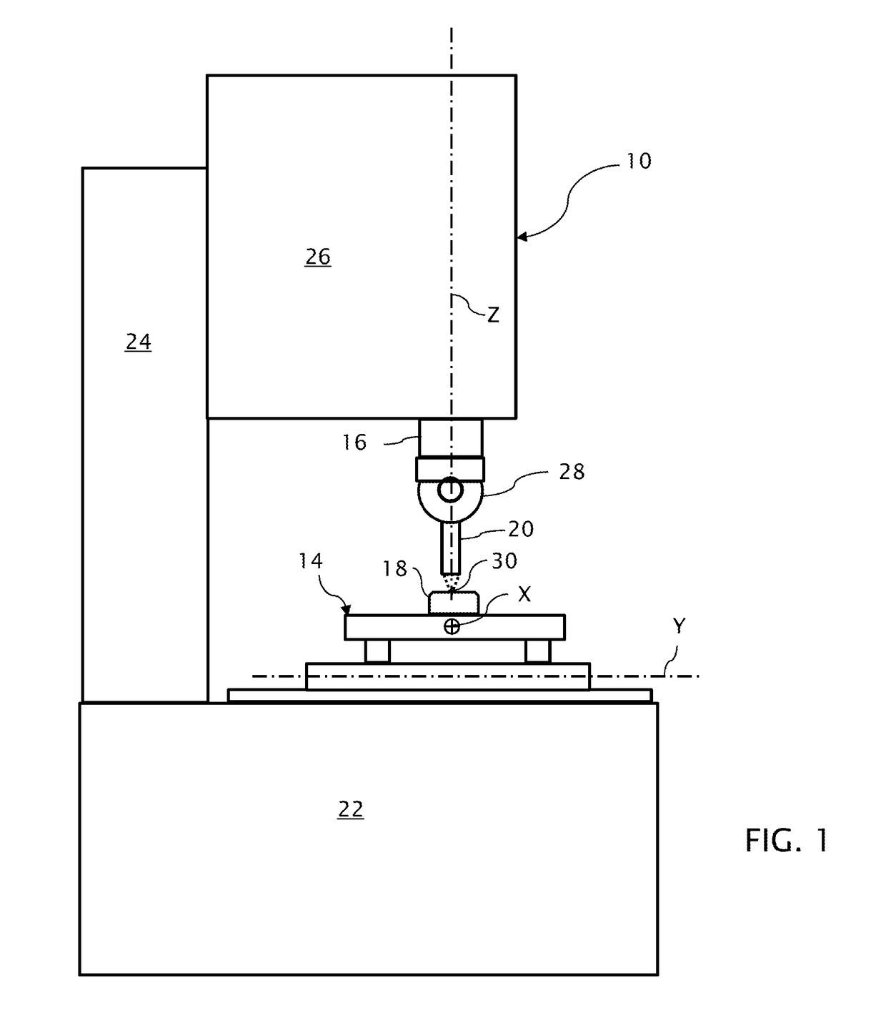
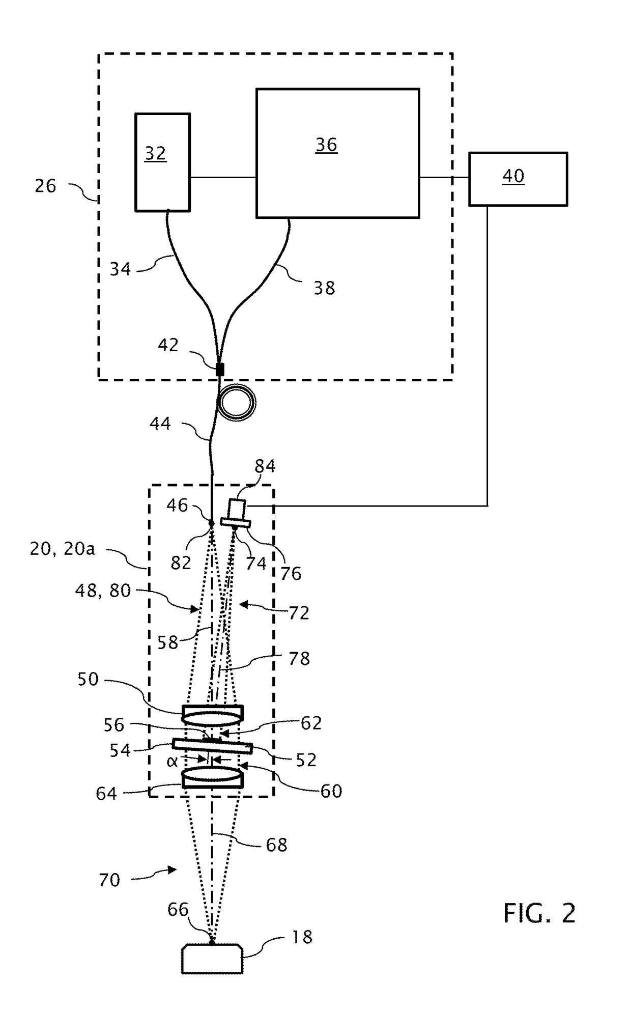
[0026]A multi-axis machine 10 depicted in FIG. 1 is one of many possible configurations of an optical measuring machine, includes an x-y stage 14 for horizontally translating a test object 18 along X and Y coordinate axes and a slide mechanism 16 for vertically translating an optical pen 20 (as the visible portion of an interferometer probe) along a Z coordinate axis. The x-y stage 14 is supported on a machine base 22. The slide mechanism 16 is supported in a slide support 26 carried on a column 24. The optical pen 20 is carried on an articulated arm 28 that is both pivotal about a horizontal axis and rotatable together with the pivot axis about the Z coordinate axis, although the optical pen 20 could be fixed mounted to the Z coordinate axis. Other unseen portions of the probe optics, including one or more light sources and a detector, or other apparatus supporting the metrology functions of the machine 10 can be housed in the slide support 26 within which the slide mechanism 16 is...


PUM


Abstract

An optical pen for an optical measurement system includes a probe body arranged to be adjustably mounted in a measuring machine for optically measuring a test object. A single mode fiber optically coupled within the pen body transmits a source beam having an instantaneous or sequentially established bandwidth spanning a range of wavelengths to the pen body and also transmits a measurement beam from the pen body toward a detector. A combination and configuration of optics within the pen body provides a more compact and efficient optical pen.

Description

TECHNICAL FIELD[0001]In the field of optical metrology, coordinate measuring machines can be arranged to acquire point-by-point interferometric measurements of test objects using optical pens for directing light to and from the test objects. Optics for producing interference as a form of measurement can be contained within the optical pens.BACKGROUND[0002]Point-by-point measurements of relative optical path length displacements can be made over a range of such optical displacements by measuring rates of interferometric phase variation with wavenumber. For example, a spatially coherent source beam composed of multiple wavelengths, i.e., a low temporally coherent beam, or a succession of different wavelengths can be divided by a beamsplitter into an object beam that is reflected from the test object and a reference beam that is reflected from a reference reflector. Reflected light from both the test object and the reference reflector is recombined at a beamsplitter into a measurement ...

Claims


Application Information

Patent Timeline
Patent Type & Authority Patents(United States)
IPC IPC(8): G01B9/02G01B11/14
CPCG01B11/14G01B9/02035G01B9/0205G01B9/0209G01B11/007G01B11/2441G02B23/24
Inventor KAY, DAVID B.
Owner QUALITY VISION INT
Why Eureka
Try Eureka