Scintillator based fiber optic plate for neutron imaging applications and the like

Active Publication Date: 2018-10-30
CONSOLIDATED NUCLEAR SECURITY
View PDF3 Cites 1 Cited by
  • Summary
  • Abstract
  • Description
  • Claims
  • Application Information

AI Technical Summary

Benefits of technology

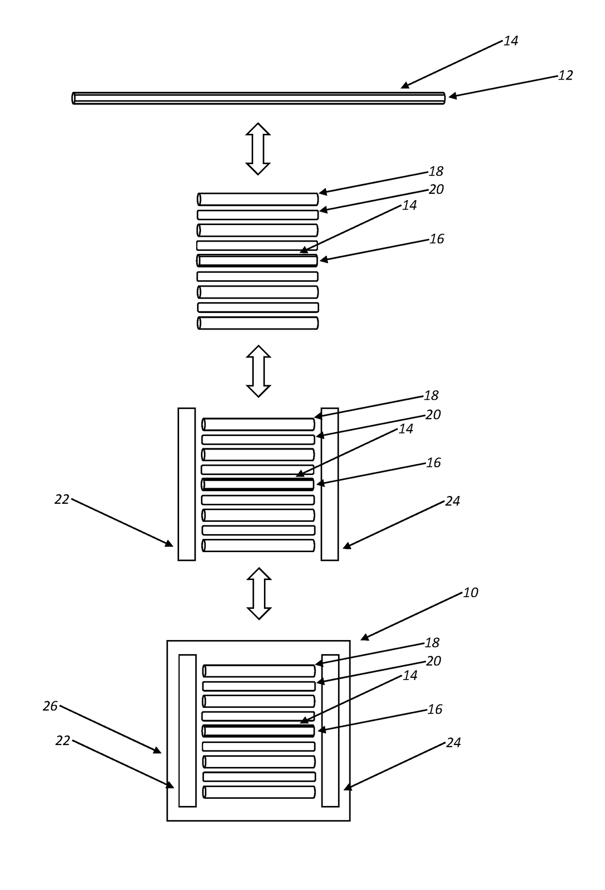
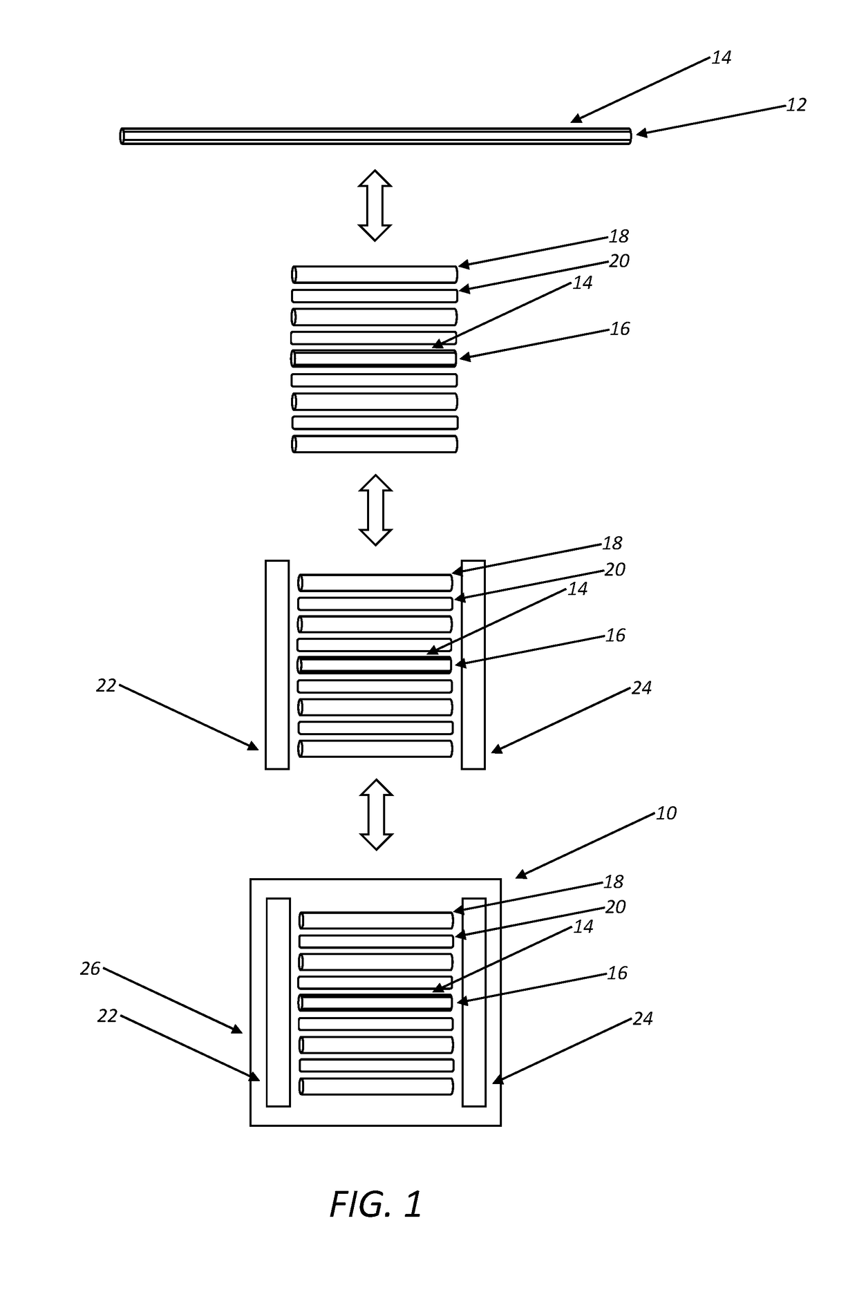
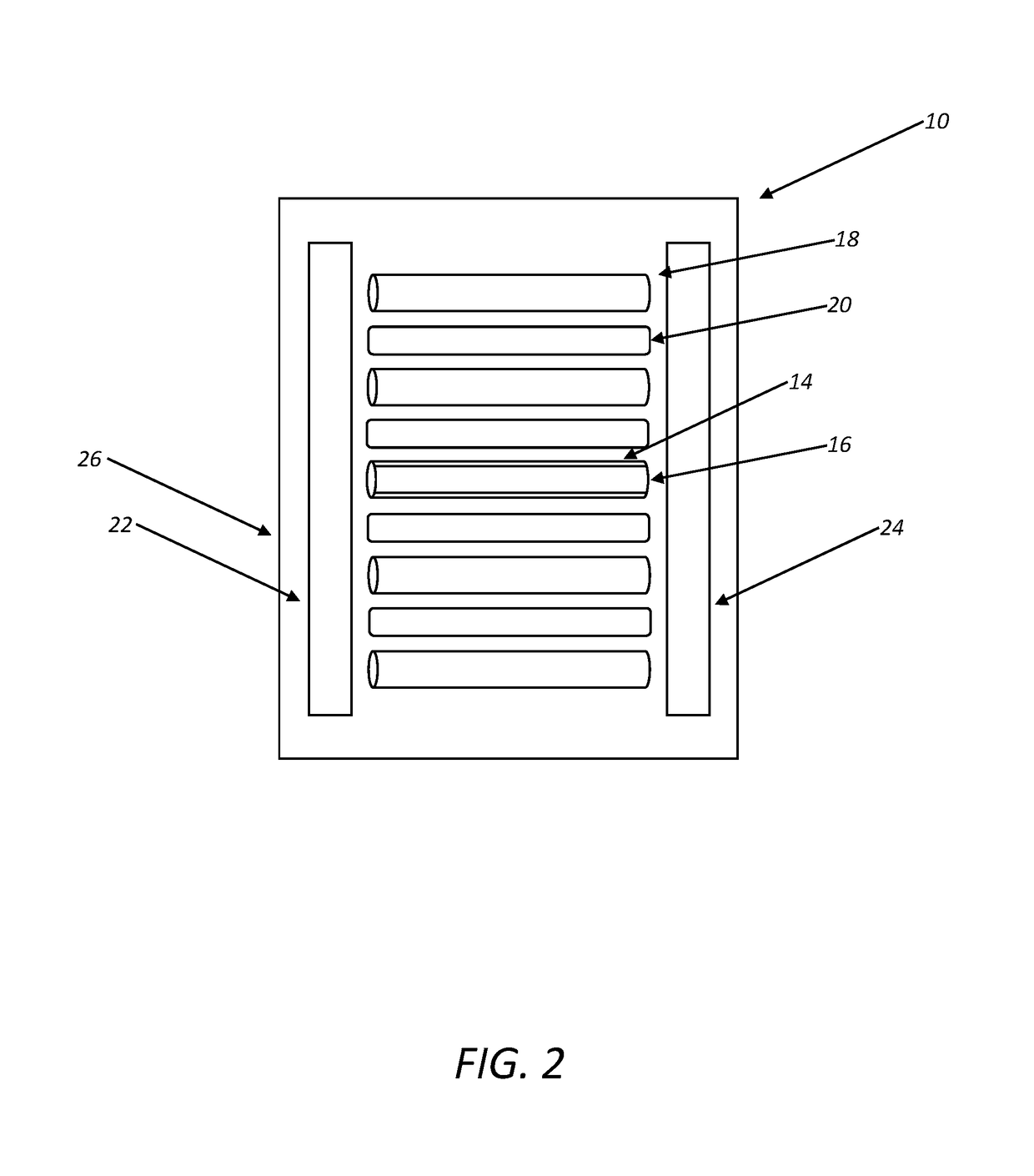
The present patent provides a fiber optic plate based on chalcopyrite, colquiriite, neutron absorber loaded glass, or plastic scintillators for neutron imaging applications. The plate has high sensitivity and resolution, and can be easily manufactured using micro-pulling-down techniques. The optical fiber segments are arranged in a parallel array and coupled together using a binder material. The fiber optic plate can be used in conjunction with a diffuse reflective material and an optical detector device for neutron imaging. The technical effects of this patent include improved sensitivity and resolution for neutron imaging applications, as well as a simplified manufacturing process.

Problems solved by technology

There is, however, no complementary system for neutron imaging applications and the like outside of high energy physics.
Although LiF—ZnS(Cu) sheets coupled to complementary metal oxide semiconductor (CMOS) panels have been used for both fast and thermal neutron imaging applications, providing high spatial resolution, they have limited efficiency due to thickness related light loss and provide slow signal development.
Similarly, thick GS20 glass detectors have been used, but provide low light output on the order of single to tens of photons and limited spatial resolution due to broadening as light traverses from the point of interaction to the readout mechanism.
Thin B-10 doped multichannel plates (MCPs) have also been used, but have limited efficiency.

Method used


Image

  • Scintillator based fiber optic plate for neutron imaging applications and the like
  • Scintillator based fiber optic plate for neutron imaging applications and the like
  • Scintillator based fiber optic plate for neutron imaging applications and the like

Examples


Embodiment Construction

[0014]In general, Stowe et al. (U.S. Pat. No. 9,334,581) provide a method for synthesizing I-III-VI2 compounds that may be used in conjunction with the present disclosure, including: (1) melting a Group III element; (2) subsequently adding a Group I element to the melted Group III element at a rate that allows the Group I and Group III elements to react, thereby providing a single phase I-III compound; and (3) subsequently adding a Group VI element to the single phase I-III compound and heating. The Group III element is melted at a temperature of between about 200 degrees C. and about 700 degrees C., for example. One (1) mole of the Group I element is added to one (1) mole of the Group III element. Preferably, the Group I element consists of a neutron absorber, such as 6Li, and the Group III element consists of In or Ga, for example. The Group VI element and the single phase I-III compound are heated to a temperature of between about 700 degrees C. and about 1000 degrees C., for exa...


PUM


Abstract

A chalcopyrite, colquiriite, neutron absorber loaded glass, or plastic scintillator based fiber optic plate for use in a neutron imaging system, including: a plurality of optical fiber segments disposed side-by-side adjacent to one another in a parallel array; and a binder material disposed between and coupling the plurality of optical fiber segments together. A diffuse reflective material is optically coupled to the plurality of first ends of the plurality of optical fiber segments. An optical detector device is optically coupled to the plurality of second ends of the plurality of optical fiber segments opposite the diffuse reflective material. Optionally, the fiber optic plate further includes a diffuse reflective material disposed one or more of on an exterior surface of each of the plurality of optical fiber segments and between the plurality of optical fiber segments.

Description

STATEMENT REGARDING FEDERALLY SPONSORED RESEARCH AND / OR DEVELOPMENT[0001]The U.S. Government has certain rights to the present disclosure pursuant to Contract No. DE-NA0001942 between the U.S. Department of Energy and Consolidated Nuclear Security, LLC.FIELD OF THE DISCLOSURE[0002]The present disclosure relates generally to neutron imaging applications and the like. More specifically, the present disclosure relates to a chalcopyrite, colquiriite, neutron absorber loaded glass, or plastic scintillator based fiber optic plate (FOP) for neutron imaging applications and the like.BACKGROUND OF THE DISCLOSURE[0003]The current state-of-the-art in medical X-ray and low energy gamma imaging applications, for example, is vapor grown, columnar CsI(TI) coupled to a conventional charge coupled device (CCD) array. There is, however, no complementary system for neutron imaging applications and the like outside of high energy physics. Although LiF—ZnS(Cu) sheets coupled to complementary metal oxide...

Claims


Application Information

Patent Timeline
IPC IPC(8): G01T3/06G01T1/20
CPCG01T1/2002G01T3/06
Inventor PRESTON, JEFFREY R.STOWE, ASHLEY C.WIGGINS, BRENDEN W.
Owner CONSOLIDATED NUCLEAR SECURITY
Why Eureka
Try Eureka