Method and thermal conductivity detector

a technology of thermal conductivity and detector, which is applied in the direction of material thermal conductivity, instruments, measurement devices, etc., can solve the problems of inability to accurately compensate the operating temperature of the heating filament due to manufacturing variations of the resistance, undesirable effort to insert a variable resistor (potentiometer) or a compensating resistance, and inability to achieve the effect of micro-machined devices including the measurement channel, facilitating thermal conductivity measurement, and reducing the number of insertions

Active Publication Date: 2018-11-13
SIEMENS AG
View PDF15 Cites 1 Cited by
  • Summary
  • Abstract
  • Description
  • Claims
  • Application Information

AI Technical Summary

Benefits of technology

[0018]The invention allows for dynamic adjustment of the operating temperature of the detector element (e.g., heating filament) to a desired value without a change in amplification or offset in the signal processing chain following the thermal conductivity detector, which inherently would add noise and wander effects.
[0019]By periodically turning the additional resistor on and off at a predetermined duty cycle and a period lower than the thermal time constant of the detector element, uncertainties in the operating temperature due to manufacturing variations of the resistances can be compensated accurately. The duty cycle may be determined in a one-time manufacturing calibration procedure and / or repeatedly in measurement calibration procedures when the detector element is exposed to only the carrier gas.
[0020]The invention further allows for dynamically changing the detector response based upon the expected peak signal without affecting the noise optimized amplifier and analog to digital converter.
[0021]For the detector element, it may be common for the constant operating temperature to be 130 to 140° C. while the gas chromatograph and sample gas to be within an oven is cooler in temperature, such as 60 to 80° C. This difference in temperature facilitates the thermal conductivity measurement and contributes strongly to the sensitivity. The invention advantageously allows for optimizing the constant operating temperature of the detector element to be high during small peaks and to be changed to a lower temperature during a large peak, so that the detector response is maximized for the subsequent ND conversion utilizing as much as the range of the A / D converter as is possible. To this end, the above-mentioned duty cycle is momentarily changed from one value to another value when predetermined ones of the analytes arrive at the detector element. Alternatively, if high-precision discrete resistors are used in the measuring bridge, thus not requiring compensation for manufacturing variations, the additional resistor is momentarily turned on each time a predetermined analyte arrives at the detector element. There are no additional elements in the signal chain (such as a gain element) that inherently would add noise and wander effects. Only the detector response is being manipulated, and the further signal processing remains unchanged with a fixed gain and associated ND converter, typically 24 bits that is performing with a SNR of 130 dB or better.

Problems solved by technology

However, a disadvantage of such a monolithic device is that manufacturing variances of the resistors do not provide a strong certainty of the exact operating temperature of the heating filament, or at the very least, a match in temperatures between successive thermal conductivity detectors, such as one in a measurement channel and another in a reference channel.
Any effort to insert a variable resistor (potentiometer) or a compensating resistance is undesirable, both from a manufacturing perspective as well as from the potential addition of undesired noise and drift.
However, this is impractical for a micromachined (MEMS) device including the measurement channel with the filament, since the channel must be enclosed about the resistance elements, thus also closed to a laser trimming operation.
The trimming operation would have to occur in an intermediate manufacturing step of the monolithic device, thus adding cost and value earlier in the process, thus running a higher risk of costly yield failures.
It is obvious that in order to account for the largest peak, the resolution of the smaller peaks will be compromised.
However, noise and wander effects are a significant challenge when performing chromatography and the variable gain amplifier would also amplify the noise and wander of the baseline of the chromatogram and thus only propagate the uncertainty of the measurement.
Variable gain electronic systems also have a tendency to add noise and wander within the very bandwidth of the low frequency chromatogram.

Method used


Image

  • Method and thermal conductivity detector
  • Method and thermal conductivity detector
  • Method and thermal conductivity detector

Examples


Embodiment Construction

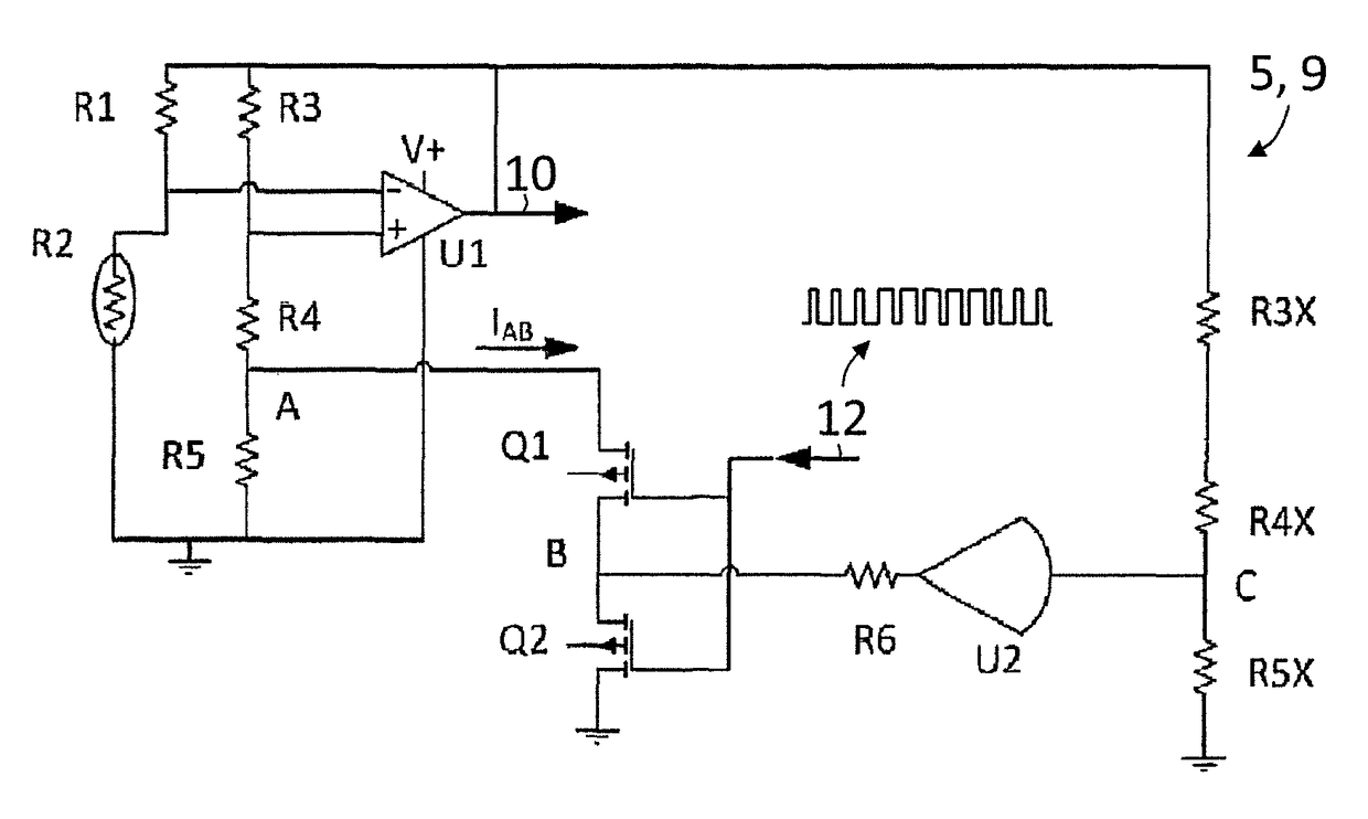
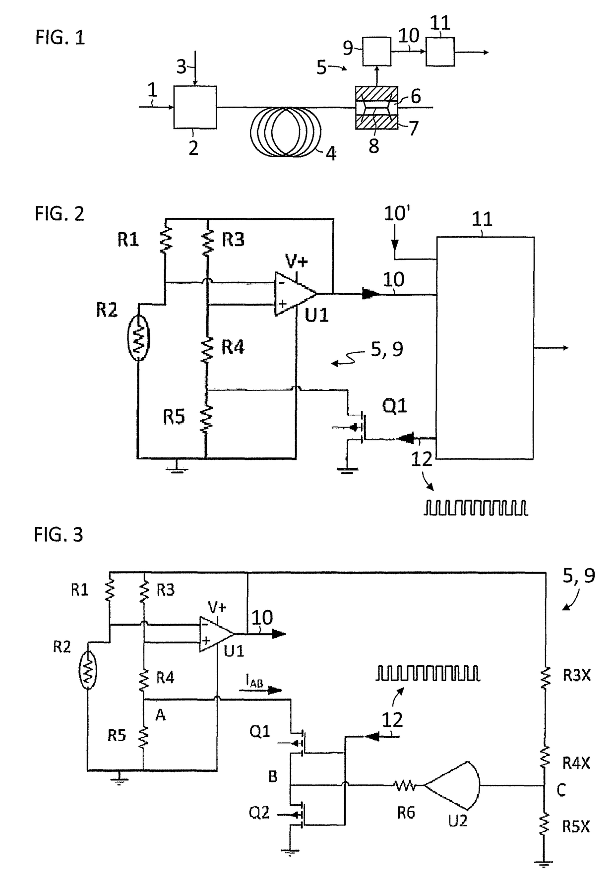
[0028]FIG. 1 illustrates a gas chromatograph in which a carrier gas 1 is delivered to an injector 2, loaded there with a sample of a gas mixture 3 to be analyzed and subsequently introduced into a separation device 4 such as a single separation column or a complete system of separation columns. The separated components or substances of the gas mixture emerging successively from the separation device 4 travel to a thermal conductivity detector 5. There, the separated gas components are conveyed in a measurement channel 6 of a measuring cell 7 past a detector element 8, such as an electrically heated heating filament. Depending on the thermal conductivity of the gas components respectively flowing past in comparison with that of the carrier gas, more or less heat is transferred from the heating filament 8 to the channel wall such that the heating filament 8 is correspondingly cooled or heated. As a result, the electrical resistance of the heating filament 8 changes, where this change ...


PUM

PropertyMeasurementUnit
temperatureaaaaaaaaaa
thermal conductivityaaaaaaaaaa

Abstract

A thermal conductivity detector includes a heatable resistive detector configured to be physically arranged in an analytes flow eluting from a chromatography column and electrically arranged with resistors in separate arms of a measuring bridge, an amplifier which detects differential voltage between two opposite nodes of the bridge and applies an output voltage to other opposite nodes of the measuring bridge to maintain the detector at a constant operating temperature, and an additional resistor with a controllable switch in parallel connected in series with the detector or resistor arranged in one arm of the bridge, where the switch is periodically turned on and off at a predetermined duty cycle and / or controlled by information on characteristic times-of-arrival of analytes at the detector to compensate for operating temperature uncertainties due to manufacturing variations of the resistors and / or to allow for processing small and large peaks of a chromatogram with highest available resolution.

Description

BACKGROUND OF THE INVENTION[0001]1. Field of the Invention[0002]The present invention relates to a thermal conductivity detector and method for operating the thermal conductivity detector.[0003]2. Description of the Related Art[0004]Thermal conductivity detectors are used to detect certain liquid or gaseous substances (fluids) based on their characteristic thermal conductivity, particularly in gas chromatography. Here, components or substances of a gas mixture are separated by passing a sample of a gas mixture in a carrier gas (mobile phase) through a separation column containing a stationary phase. The different components interact with the stationary phase that causes each component to elute at a different time, which is known as the retention time of the component. The separated substances, also referred to as analytes, are detected by a thermal conductivity detector which has a measuring cell with an appropriate detector element, e.g., an electrically heated filament disposed in...

Claims


Application Information

Patent Timeline
Patent Type & Authority Patents(United States)
IPC IPC(8): G01N30/00G01N25/18G01N27/18G01N30/66G01N30/62G01N30/02
CPCG01N30/62G01N25/18G01N30/66G01N27/18G01N2030/625G01N2030/025G01N2030/621
Inventor GELLERT, UDOSCHMIDT, GLEN EUGENE
Owner SIEMENS AG
Why Eureka
Try Eureka