Method and MIMO radar device for determining a position angle of an object

a technology of position angle and radar device, which is applied in the direction of measurement device, using reradiation, instruments, etc., can solve the problems of residual phase shift which has an adverse effect on the subsequent position angle determination, and achieve the effect of increasing angular accuracy and large apertur

Active Publication Date: 2018-11-13
ROBERT BOSCH GMBH
View PDF11 Cites 6 Cited by
  • Summary
  • Abstract
  • Description
  • Claims
  • Application Information

AI Technical Summary

Benefits of technology

[0019]The method according to the present invention may be carried out without phase coherence of the switching states of the transmitting antennas, in particular without phase coherence of the emitted radar signals, so that, for example, even comparatively slow FMCW ramps are emittable as radar signals, and are evaluatable when reflected on the object. The angle-dependent amplitude differences of the transmitting antennas are utilized according to the present invention for ambiguity resolution, i.e., for distinguishing between multiple objects, and / or for increasing the angular accuracy. Accordingly, ambiguous receiver arrays, i.e., arrangements of receiving antennas of the MIMO radar device having a relatively large aperture, may be used, since the ambiguities as described above are resolved via the amplitude differences of the transmission states, i.e., the radar signals.
[0020]According to one preferred refinement, the first angle and the second angle are equal. According to another preferred refinement, the first angle is smaller than the second angle.
[0024]According to one preferred refinement, the MIMO radar device according to the present invention includes a fourth transmitting antenna with the aid of which fourth radar signals are emittable having a fourth radiation pattern, a main lobe of the fourth radiation pattern pointing in a fourth direction which is at a third angle of between 1 degree and 90 degrees relative to the third direction.

Problems solved by technology

Errors in the speed estimation result in residual phase shifts which have an adverse effect on the subsequent position angle determination, in particular if radar signals having relatively slow FMCW ramps are emitted.

Method used


Image

  • Method and MIMO radar device for determining a position angle of an object
  • Method and MIMO radar device for determining a position angle of an object
  • Method and MIMO radar device for determining a position angle of an object

Examples


second specific embodiment

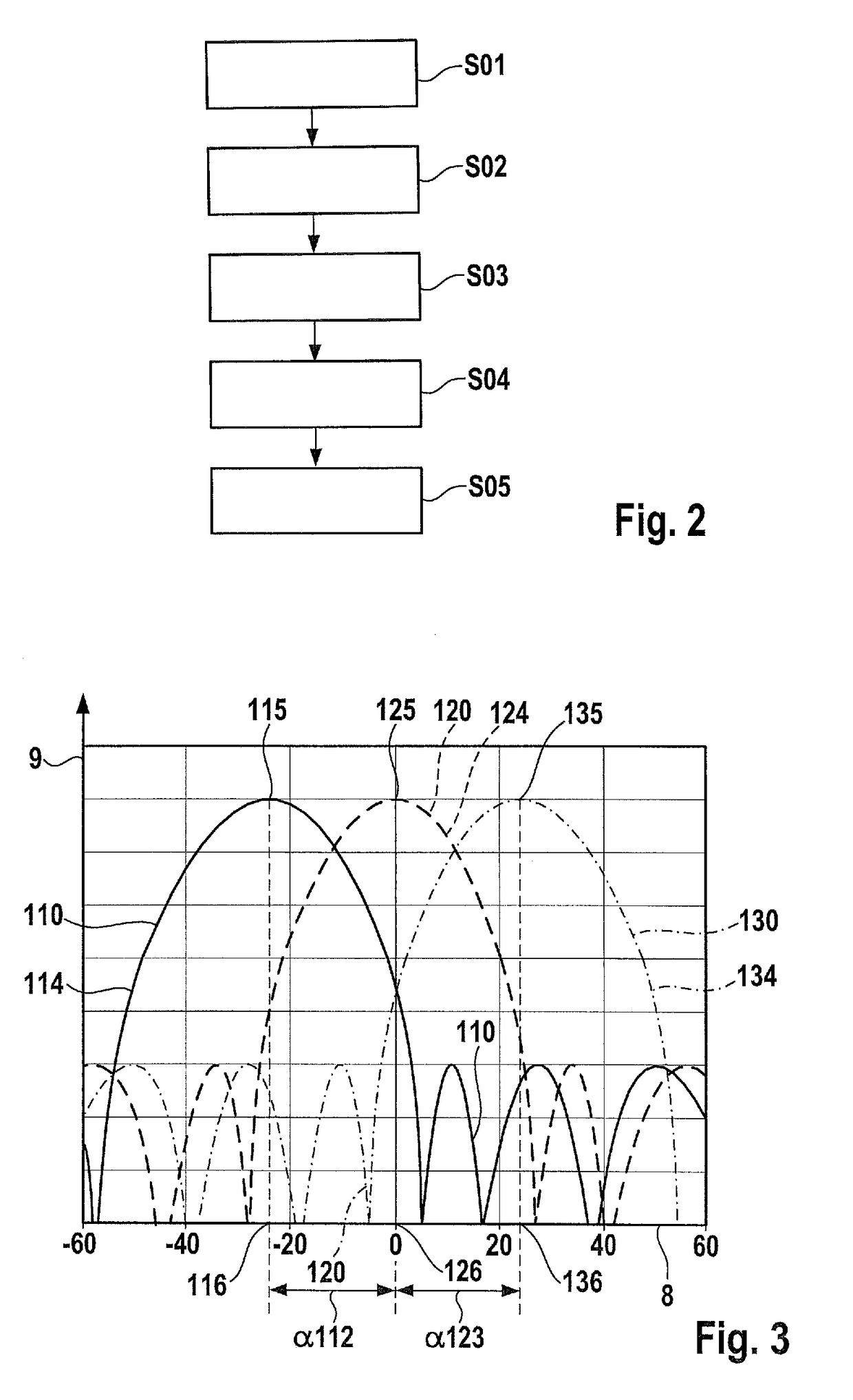
[0045]FIG. 3 shows a schematic graph for explaining a method for determining a position angle θ of an object 5 according to the present invention.

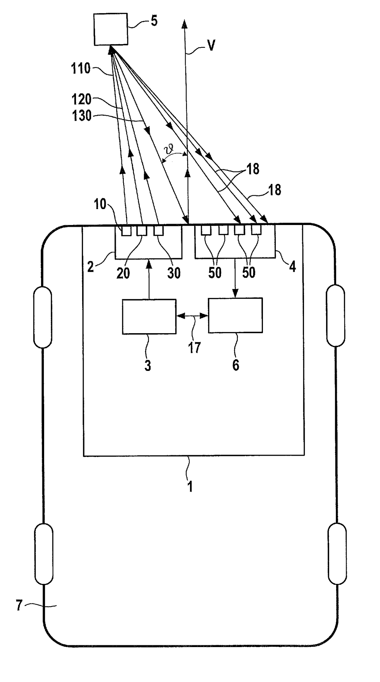
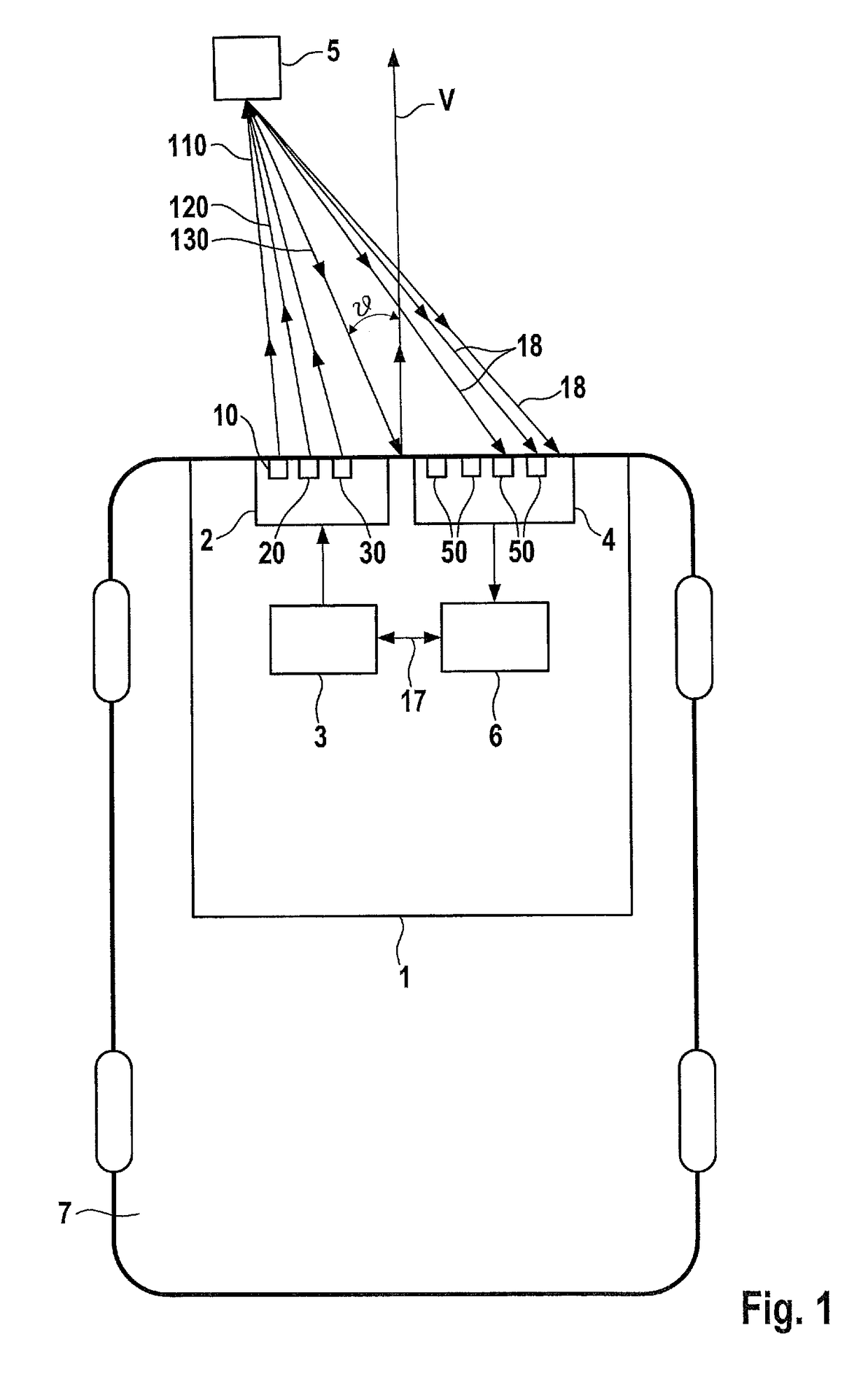
[0046]Directions of the angle at which main lobes 114, 124, 134 of first through third radiation patterns 112, 122, 132 of first through third transmitting antennas 10, 20, 30 are oriented according to the present invention are provided on a horizontal axis 8. When correctly adjusted, the direction at 0° along horizontal coordinate axis 8 points exactly in forward travel direction V of vehicle 7. In this case, negative angles along horizontal coordinate axis 8 refer to directions “to the left” ahead of vehicle 7, and positive angles refer to directions “to the right” ahead of vehicle 7.

[0047]Power is plotted on a vertical coordinate axis 9. The curves of first, second, and third radar signals 110, 120, 130 thus denote the power which is emitted when first through third radar signals 110, 120, 130 are emitted in certain directions, i.e., an...


PUM


Abstract

A method and a MIMO radar device are provided for determining a position angle of an object. The method includes the following steps: emitting a first radar signal with the aid of a first transmitting antenna having a first radiation pattern; emitting a second radar signal with the aid of a second transmitting antenna having a second radiation pattern; emitting a third radar signal with the aid of a third transmitting antenna having a third radiation pattern; the first, second, and third radar signal being emitted in various directions; receiving radar signals which are reflected on the object; and determining the position angle of the object based on phase differences and based on amplitude differences, which originate from the emission of the radar signals in the first through third directions, between the received reflected radar signals.

Description

FIELD OF THE INVENTION[0001]The present invention relates to a method and a MIMO radar device for determining a position angle of an object. The MIMO radar device may be situated in particular in a vehicle, such as a road vehicle, rail vehicle, aircraft, or watercraft. The position angle of an object is understood in particular to mean that angle at which the object is situated in relation to a reference axis. For applications in a vehicle, this is preferably the forward travel direction, centered on the middle of the vehicle in the transverse direction. Reference to an angular dependency below is understood to mean a dependency on the position angle. The position angle may in particular be the so-called azimuth angle, which is based on a vehicle.BACKGROUND INFORMATION[0002]In technical usage, MIMO stands for “Multiple Input Multiple Output,” and refers to a system or method according to which multiple transmitting antennas and multiple receiving antennas are used for achieving an e...

Claims


Application Information

Patent Timeline
Patent Type & Authority Patents(United States)
IPC IPC(8): G01S13/93G01S13/44G01S7/282G01S5/06G01S13/42G01S5/04G01S7/35G01S13/931
CPCG01S7/35G01S13/42G01S13/931G01S13/4454G01S5/06G01S7/282G01S13/4445G01S5/04G01S7/02G01S13/02
Inventor LOESCH, BENEDIKTSCHOOR, MICHAEL
Owner ROBERT BOSCH GMBH
Why Eureka
Try Eureka