
Dielectric fuse memory circuit and operation method thereof

a dielectric fuse and memory circuit technology, applied in the field of memory, can solve the problems of poor retention, charge loss, and existing products that require further improvement, and achieve the effects of improving the quality of existing products, and improving the efficiency of existing products

Active Publication Date: 2018-11-13
NAT CHIAO TUNG UNIV
View PDF62 Cites 3 Cited by
  • Summary
  • Abstract
  • Description
  • Claims
  • Application Information

AI Technical Summary

Benefits of technology

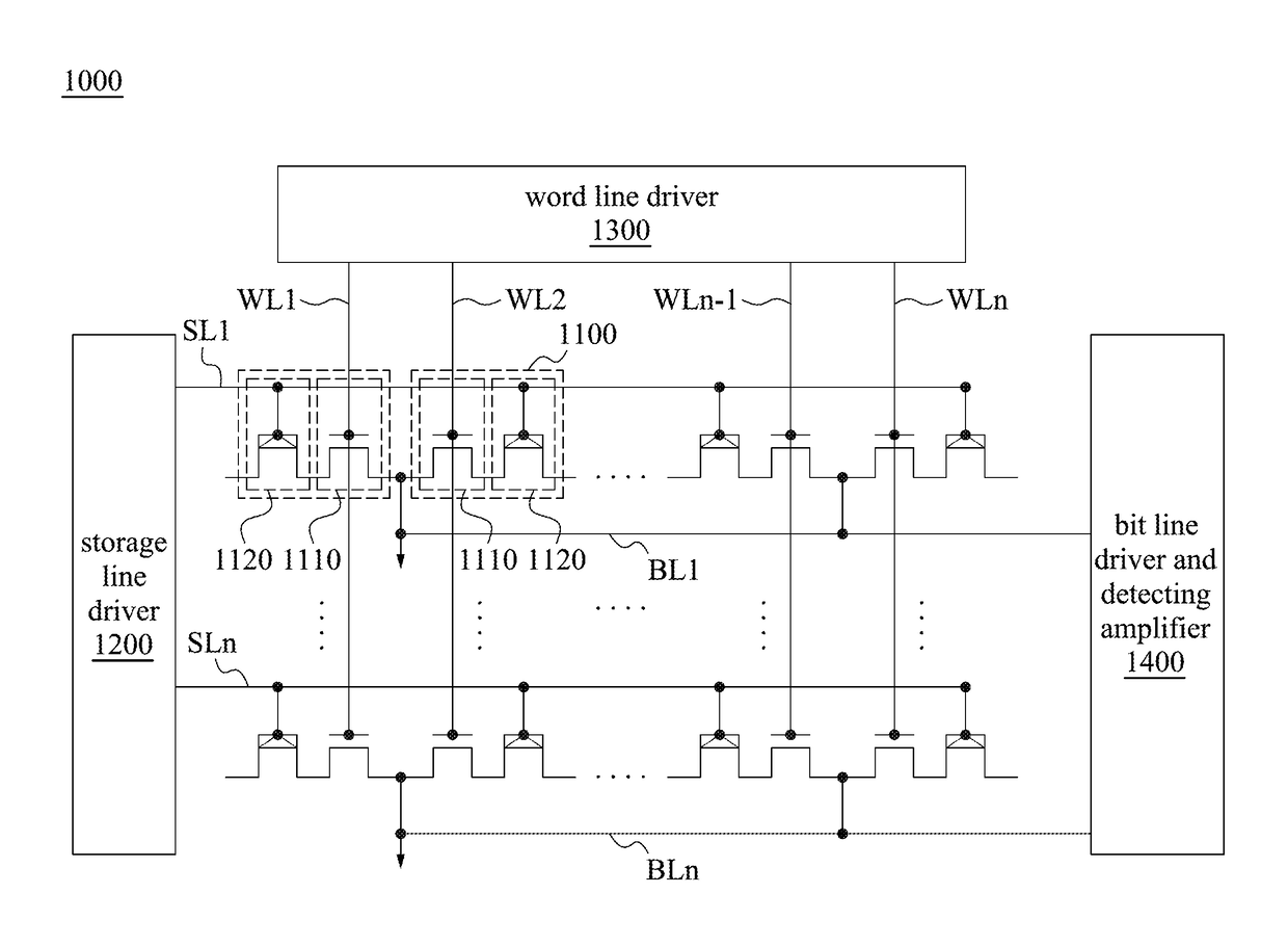
The present disclosure is related to an integrated circuit memory that includes multiple memory cells. Each cell has a first field-effect transistor and a second field-effect transistor. The first field-effect transistor has a first region, a second region, and a third region. The third region is connected to the first region and the second region. The first field-effect transistor also has at least one gate dielectric layer and at least one gate electrode layer. The second field-effect transistor has a first region, a second region, and a third region. It also has at least one gate dielectric layer and at least one gate electrode layer. The first field-effect transistor and the second field-effect transistor share the second region. The second field-effect transistor is connected to the ground line. The first field-effect transistor and the second field-effect transistor have a ground terminal. The first field-effect transistor and the second field-effect transistor are connected to different decoding lines. Applying an electric signal to the decoding lines results in a change in the conductivity of the gate dielectric layer of the second field-effect transistor, which can be sensed to store information. The technical effect of this disclosure is to provide a more efficient and reliable integrated circuit memory that can store information with high accuracy and reliability.

Problems solved by technology

However, its drawback is charge loss and yields to poor retention.
In view of the foregoing, problems and disadvantages are associated with existing products that require further improvement.
However, those skilled in the art have yet to find a solution.

Method used


Image

  • Dielectric fuse memory circuit and operation method thereof
  • Dielectric fuse memory circuit and operation method thereof
  • Dielectric fuse memory circuit and operation method thereof

Examples


Embodiment Construction

[0039]The detailed description provided below in connection with the appended drawings is intended as a description of the present examples and is not intended to represent the only forms in which the present example may be constructed or utilized. The description sets forth the functions of the example and the sequence of steps for constructing and operating the example. However, the same or equivalent functions and sequences may be accomplished by different examples.

[0040]Unless otherwise defined herein, scientific and technical terminologies employed in the present disclosure shall have the meanings that are commonly understood and used by one of ordinary skill in the art. Unless otherwise required by context, it will be understood that singular terms shall include plural forms of the same and plural terms shall include singular forms of the same.

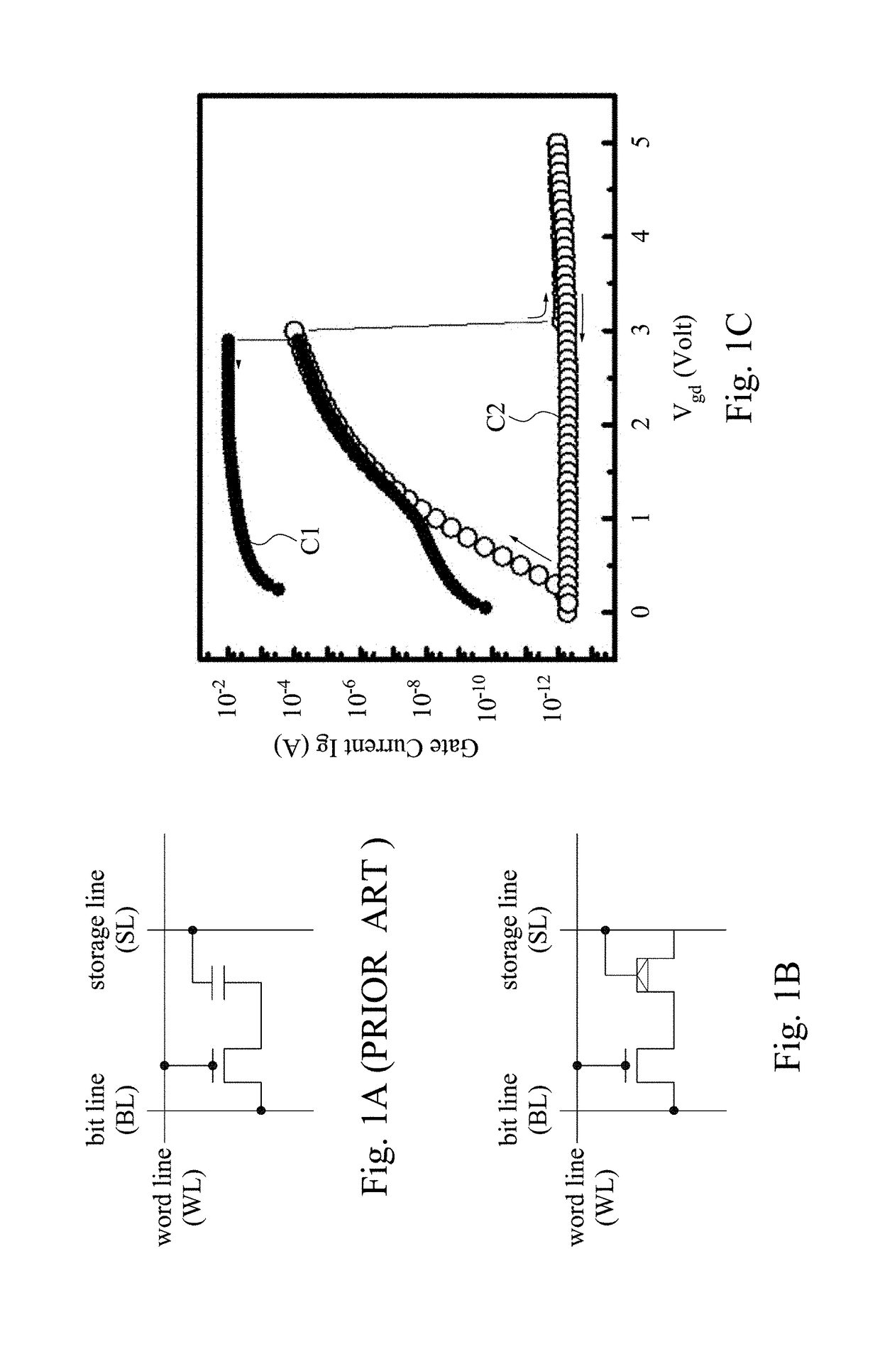
[0041]Different from conventional anti-fuse dielectric memory as shown in FIG. 1A, the memory of the present disclosure is basically co...


PUM


Abstract

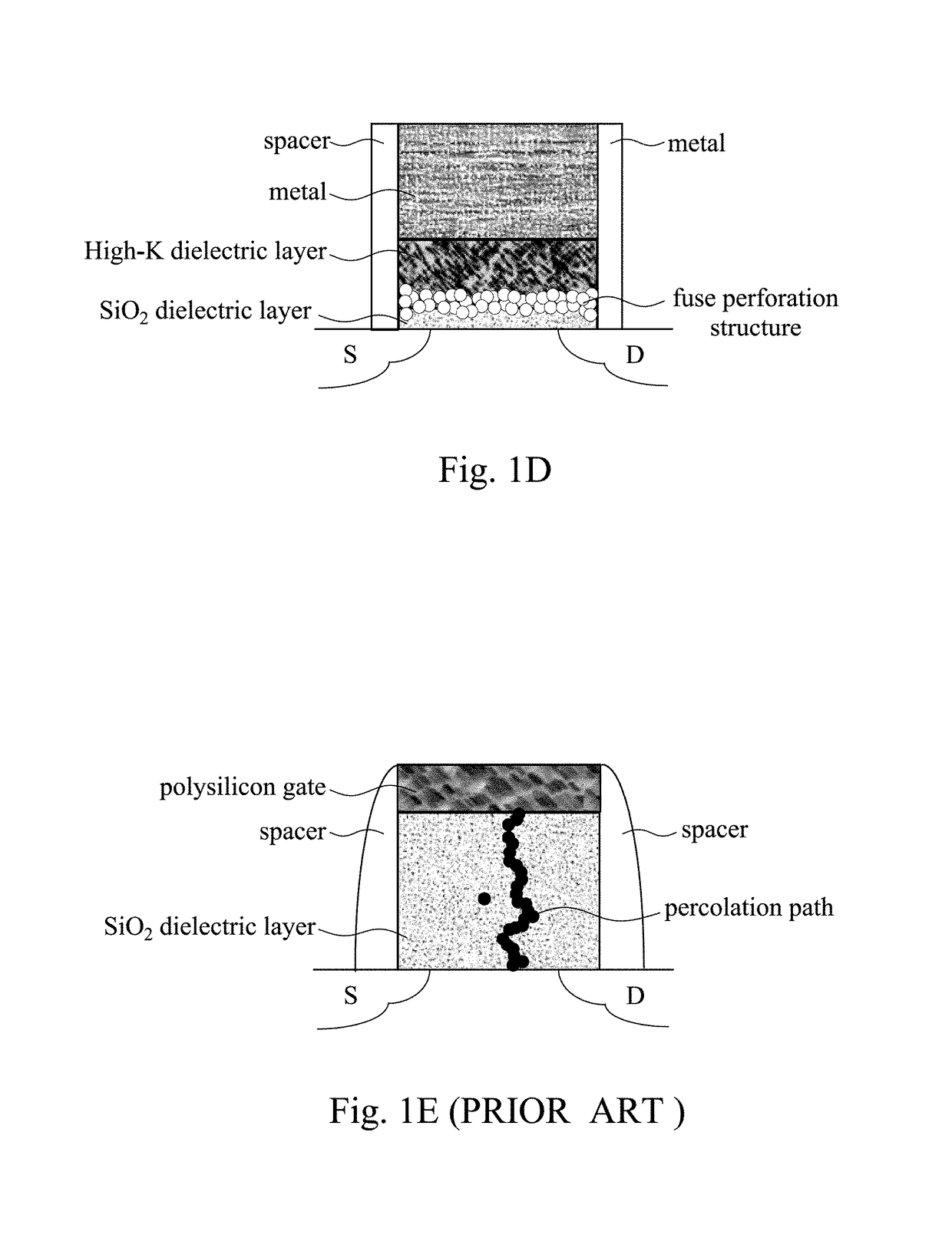
One time programming and repeatably random read integrated circuit memory has a storage device that programs the information by using dielectric-fuse mechanism. The main characteristics of dielectric fuse mechanisms is that by applying an electric field on the dielectrics, the ions or atoms in the dielectrics are drifted-out, or the dielectrics are burned-out, that create damage of the dielectric structure in a form of porosity, and the conductivity (resistivity) of tunneling current through the dielectrics changes the state from high conductivity (resistivity) to low conductivity (resistivity). The dielectric fuse mechanism has been integrated in VLSI circuits, completed the validation, and implemented by the fabrication of CMOS process.

Description

RELATED APPLICATIONS[0001]This application claims priority to U.S. Provisional Application Ser. No. 62 / 198,666, filed Jul. 29, 2015, which is herein incorporated by reference.BACKGROUND[0002]Field of Invention[0003]The present invention relates to a memory. In particular, the present invention relates to one-time programming and repeatedly random read integrated circuit memory.[0004]Description of Related Art[0005]One time programming (OTP) memory and multi time programming (MTP) memory have three main kinds as shown below. The first kind memory is a traditional kind memory that metal atomic in the metal connection will be moved due to electromigration when there is a high current, thereby the metal connection is disconnected so as to form fuse-type wire memory. It can be implemented by Al / Cu / Silicide liner, poly-Si liner, contact via, or metal gate liner.[0006]The second kind memory is that as the thickness of the gate dielectric layer is getting thinner, the breakdown electric fie...

Claims


Application Information

Patent Timeline
Patent Type & Authority Patents(United States)
IPC IPC(8): G11C17/18H01L27/112G11C17/16G11C16/04H01L23/525
CPCG11C17/18G11C17/16H01L27/11206H01L23/5256G11C16/0433H10B20/25
Inventor CHUNG, STEVE S.HSIEH, E-RAYHUANG, ZHI-HONG
Owner NAT CHIAO TUNG UNIV
Learn More