
Wall made from a composite material reinforced so as to limit the spread of a crack in a direction

a composite material and reinforcement technology, applied in the direction of synthetic resin layered products, transportation and packaging, efficient propulsion technologies, etc., can solve the problems of cracks spreading from a localized damage area, panels are not resilient and may break, and wires of the mesh would create aerodynamically prohibitive protrusions, so as to facilitate crack deflection and limit adhesion

Active Publication Date: 2018-12-04
AIRBUS OPERATIONS (SAS)
View PDF11 Cites 0 Cited by
  • Summary
  • Abstract
  • Description
  • Claims
  • Application Information

AI Technical Summary

Benefits of technology

The invention proposes a wall made from a composite material reinforced to limit the spread of a crack in a specific direction without adding excessive weight to the aircraft. The metal reinforcement is designed to be immobilized between the layers of fibers, allowing for limited adhesion with the adjacent layers while still deflecting the crack in the direction of the reinforcement. This feature helps to reinforce the wall without adding too much weight to the aircraft.

Problems solved by technology

Beyond that, the wires of the mesh would create aerodynamically prohibitive protrusions.
However, these panels are not resilient and may break in the event of impact.
Lastly, cracks may spread from a localized damage area along an uncontrolled path.
However, in case of incidents, if the structure of the aircraft to which the acoustic panel is connected tends to deform, the stresses borne by the panel may cause fissures or cracks to appear, which may spread if the burdens are severe enough, thereby causing the panel to break into several parts.
However, these parts made from a composite material have a low resistance to limit the risks of a crack spreading in a transverse plane that may then extend over the entire circumference.
This panel may not be used for applications where it is in contact with aerodynamic flows, due to the protruding elements.

Method used


Image

  • Wall made from a composite material reinforced so as to limit the spread of a crack in a direction
  • Wall made from a composite material reinforced so as to limit the spread of a crack in a direction
  • Wall made from a composite material reinforced so as to limit the spread of a crack in a direction

Examples


Embodiment Construction

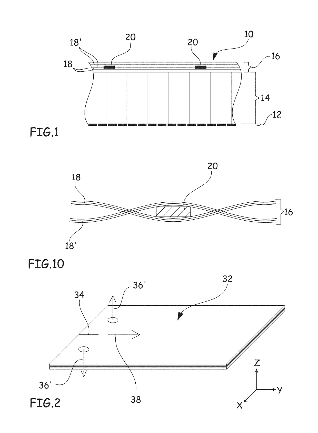
[0040]FIG. 1 shows an acoustic treatment panel 10 including, from the outside toward the inside, an acoustically resistive porous layer 12, at least one cellular structure 14, and a reflective or impermeable wall 16.

[0041]The acoustically resistive layer 12 and the cellular structure 14 are not described in more detail, as they are known by those skilled in the art and can be made in the same way as those of the acoustic treatment panels according to the prior art.

[0042]The acoustically resistive layer 12 and the cellular structure 14 can be made from a composite material. The reflective wall 16 is made from a composite material. It comprises at least two layers of fibers 18, 18′ oriented parallel to the plane of the panel and embedded in a resin matrix.

[0043]According to one embodiment, the reflective wall 16 comprises at least two layers of fibers 18, 18′, which may or may not be woven, and may or may not be pre-impregnated, the layers being draped on one another. The wall may com...


PUM

PropertyMeasurementUnit
Fractionaaaaaaaaaa
Thicknessaaaaaaaaaa
Widthaaaaaaaaaa

Abstract

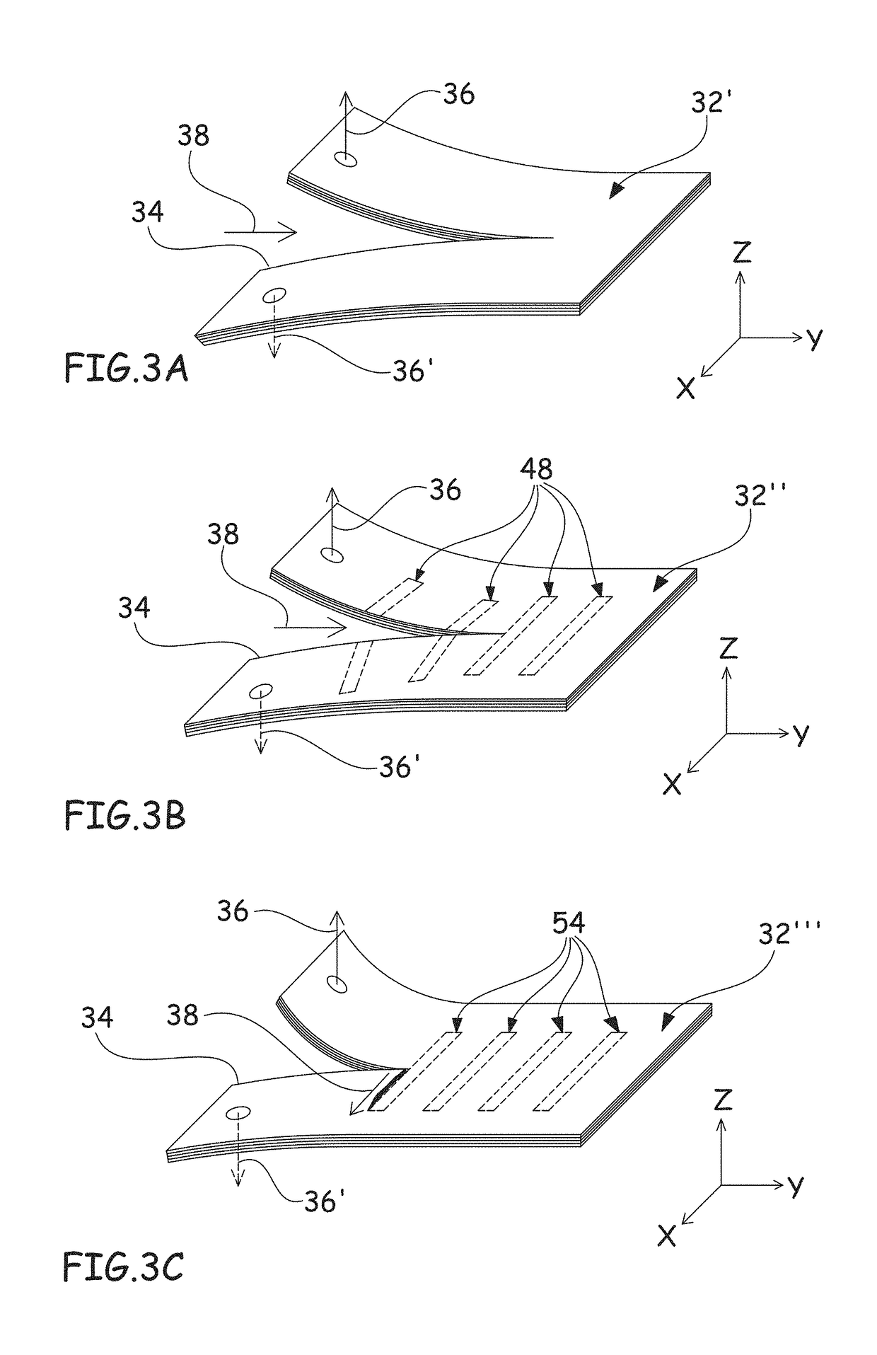
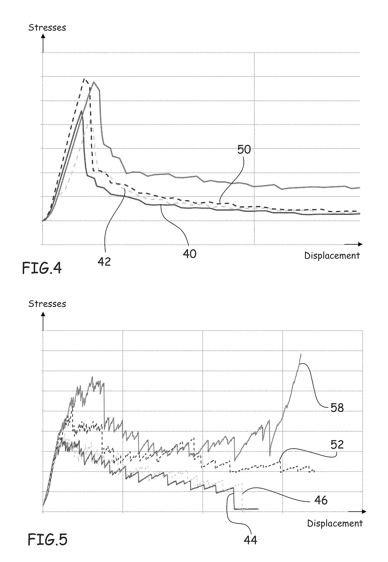
The invention relates to a wall made from a composite material comprising at least two layers of fibers (18, 18′) embedded in a resin matrix, a crack being able to spread in said wall in a direction of propagation, characterized in that it comprises at least one longilineal metal reinforcement (20), oriented in a direction secant to the direction of propagation, inserted between two layers of fibers (18, 18′) of the wall.

Description

[0001]This application and claims priority to FR 1161514 filed 13 Dec. 2011, the entire contents of which is hereby incorporated by reference.BACKGROUND[0002]The present invention relates to a wall made from a composite material reinforced so as to limit the spread of a crack in a given direction.[0003]To limit the impact of noise annoyance in aircrafts, techniques have been developed to reduce the noise, in particular by positioning panels or coatings at certain walls aiming to absorb some of the sound energy, in particular using the principle of Helmholtz resonators.[0004]This type of panel comprises, from the outside toward the inside, an acoustically resistive porous layer, at least one cellular structure, and a reflective or impermeable wall. Alternatively, the panel may comprise several superimposed cellular structures between which acoustically resistive porous layers are provided. The cells of the cellular structure(s) are sized so as to ensure optimal acoustic treatment.[00...

Claims


Application Information

Patent Timeline
IPC IPC(8): B64C1/40B32B3/08B32B27/08B64D33/02B64C1/00
CPCB64C1/40B32B3/08B32B27/08B32B2262/00B32B2307/5825B32B2605/18B64C2001/0072B64D2033/0206Y02T50/433Y10T428/249921Y02T50/40
Inventor PORTE, ALAINLALANE, JACQUESDIDA, STÉPHANE
Owner AIRBUS OPERATIONS (SAS)
Learn More