Device for preparing biological samples

a biological sample and device technology, applied in the field of microbiological analysis, can solve the problems of difficult collection of particles of interest or microorganisms retained on the filter paper, inability to achieve optimal concentration ratio, and rapid blockage of filters, so as to simplify the process of filtration of biological samples, the effect of limiting the adhesion to the wall and easy us

Active Publication Date: 2018-05-01
BIOMERIEUX SA
View PDF10 Cites 2 Cited by
  • Summary
  • Abstract
  • Description
  • Claims
  • Application Information

AI Technical Summary

Benefits of technology

[0075]Preferentially, the filtering means and the wall of the collecting tank are in contact over the entire surface area of the filtering means. The advantage of this contact over the entire surface area of the filtering means is to limit the adhesion to the wall of any debris contained in the biological sample and to simplify the process of filtration of the biological sample, it being possible for said sample to be distributed anywhere in the collection area of the collecting tank, in particular on the wall or directly on the filtering means.
[0076]As the jets of collecting buffer are delivered, the microorganisms concentrate toward the bottom part of the filtering means forming, for example, a closed angle with the wall of the collecting tank. A bacterial concentrate can, for example, be recovered without significant loss of volume (volume recovered from 300 to 700 μl), relative to the volume of collecting buffer dispensed (volume 400 to 1000 μl), i.e. a factor of 10 to 20 relative to the initial volume of biological sample. The incline of the second plane of the filtering means relative to the plane of the base of the fixed support can be between 10° and 60°, preferably between 20° and 50°, preferably between 25° and 45°, more preferentially equal to 30°.
[0077]The device according to the invention can be readily used with an automated pipette, also called pipetting robot. For this purpose, the wall of the collecting tank is designed so as to be able to vertically present a tool for a pipetting robot, such as a pipette or a swab, in line with the entire surface of the filtering means of the collecting tank directly after or during the filtration step. The advantage is that of not having to move the device, the collecting tank and / or the filtering means in order to collect the concentrate of constituents of interest. Another advantage is that of being able to collect, by abrasion or detachment, the concentrate of constituents of interest, such as microorganisms, deposited on all or part of the filtering means, after filtration, by means of a swab. This geometry also facilitates the manual and / or automatic pipetting and / or swabbing operations, in particularly directly after or during the filtration step. Thus, the shape of the wall of the collecting tank is designed so that an operator or a pipetting robot can have access to the entire surface area of the filtering means of the collecting tank, in particular vertically with respect to said filtering means. A pipetting robot in fact has a pipette which moves translationally according to three degrees of freedom and which does not make it possible to make complex movements or to present a pipette other than vertically.
[0078]This access to the entire surface area of the filtering means of the collecting tank thus makes it possible to dispense a liquid on an area of the filtering means of the collecting tank with a powerful jet and then to suction this same liquid in order to be able to powerfully redispense it on another area of the filtering means of the collecting tank. A series of about twenty dispensing / resuctioning operations can thus be carried out in order to concentrate and then harvest the constituents of interest retained on the entire surface area of the filtering means of the collecting tank. The incline of the collecting tank additionally allows the collection liquid to localize in the preferential collecting area while limiting the losses of volume that would be created by a horizontal filtration system.
[0079]Advantageously, the wall of the collecting tank can have at least one part which is inclined, or in the shape of a pointed arch, designed to be able to vertically present a pipette, in line with the concentrate of constituents of interest, in particular of microorganisms, the concentrate being predominantly located in the preferential area. This geometry also facilitates the manual and / or automatic pipetting and / or swabbing operations, in particular by preventing striking of the wall of the collecting tank.
[0080]The advantage of such a device is that it can be used, on the same type of device, for various types of biological samples (urine, blood cultures, etc) of different volumes (10 ml to 1 ml), by selecting a treatment protocol suitable for the biological sample under consideration. Thus, for blood cultures, the protocol is a selective lysis followed by a single filtration on a filtering means, for example a membrane. For clinical urine, the protocol consists of a prefiltration on the filtering means of the prefiltration tank, followed by a filtration on the filtering means of the collecting tank, for example on a membrane. The two protocols can advantageously be followed by one or more steps of washing the bacterial concentrate using suitable washing solutions.

Problems solved by technology

Indeed, the filter can become rapidly blocked if the liquid contains too many particles or microorganisms, which can prevent filtration of the entire volume.
Furthermore, the large filtration surface area, required in order to be able to filter a sufficient amount of sample, can require the use of a large volume of liquid for completely resuspending the microorganisms retained on the filter, which does not make it possible to have an optimal concentration ratio.
After having filtered the sample by means of this device, the collection of particles of interest or microorganisms retained on the filter paper is difficult and requires the manual use of a swab.
It is not easy to reproducibly perform the recovery by swab automatically.
Furthermore, this type of device has an unfavorable second release yield if the concentrate, in particular bacterial concentrate, must be provided in liquid form for the needs of the analysis protocol.
Finally, during the steps of washing the filter or of taking up the microorganisms with a pipette, the liquid dispensed spreads over the entire surface of the filter, and it is therefore difficult to again suction it.
As a result, the sequence of a filtration protocol using this device cannot be easily automated.
Although this device can have a better filtration yield, in particular if progressive filtrations are carried out, the liquid dispensed also spreads over the entire surface of the two membranes, making collection difficult.
Furthermore, blocking, even partial, of one or more membrane(s) can lead to a pressure drop during suctioning and slow down or even prevent filtration.

Method used


Image

  • Device for preparing biological samples
  • Device for preparing biological samples
  • Device for preparing biological samples

Examples


example 1

ts in Inoculated Urine: Results on Three Microorganisms in Automatic Mode

[0186]Microorganisms EC (Escherichia coli), SE (Staphylococcus epidermidis) and CA (Candida albicans).

[0187]

TABLE 3Yield of recovery (%) of the microorganismsE.C, S.E and C.A on several replicatesMOReplicateECSECA110037122784420388351849240959138867715

[0188]The yield is defined as the ratio of the amount of microorganisms recovered on the membrane at the end of the protocol to the amount of microorganisms introduced in solution on the prefilter.

[0189]This experiment, illustrated in FIG. 17, makes it possible to conclude that the device according to the invention is operating correctly. It makes it possible to effectively filter 10 ml of urine and to collect a not insignificant fraction of the microorganisms therefrom.

example 2

ts in Inoculated Healthy Urine: On Automated Pipetting Device (4 Parallel Devices)

[0190]Filtration yield on the EC (Escherichia coli) and CA (Candida albicans) microorganisms for various resuspension configurations (volume and distance to the vertical of the filter).

[0191]

Average yield on4 samplesECCASmall-volume jet69%29%and distance 1 mmSmall-volume jet59%and distance 3 mmLarge-volume jet73%27%and distance 3 mmLarge-volume jet59%and distance 5 mmManual reference82%

[0192]Table 4 showing the yield of recovery of the microorganisms E.C and C.A on several replicates while varying the automated resuspension method

[0193]This experiment made it possible to come to a conclusion regarding the feasibility of automation of the device and regarding the impact of the type of resuspension on the recovery yield.

Example 3: Experiment with Pathological Urine: Results of Detection of E. coli Peptides by LC-ESI MS (MRM Mode)

[0194]A batch of fifteen pathological urines was treated by double filtratio...

example 4

t with Inoculated Blood Cultures: Results of Peptide Detection by LC-ESI MS (MRM Mode)

[0215]The lysis-filtration protocol consists briefly of a selective lysis of the blood cells by action of a buffer containing a surfactant for a short period of time.

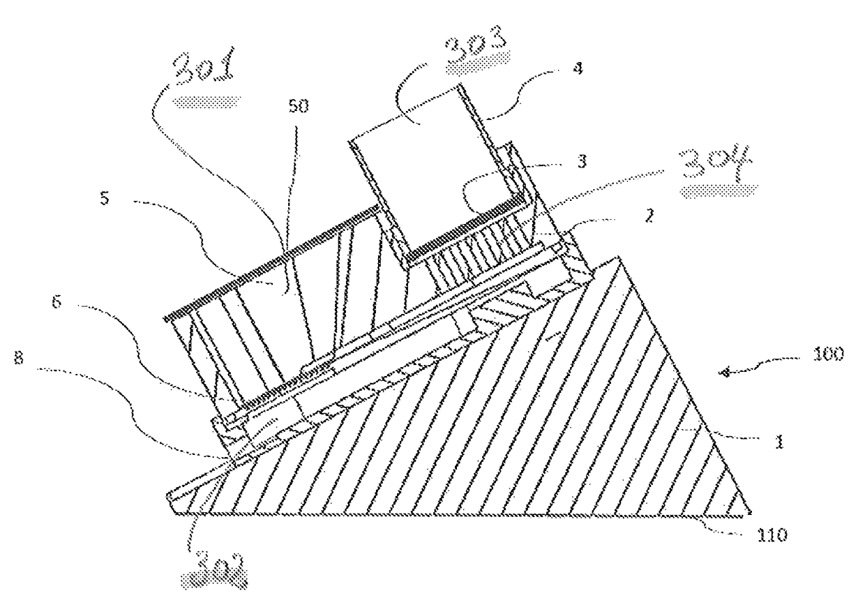
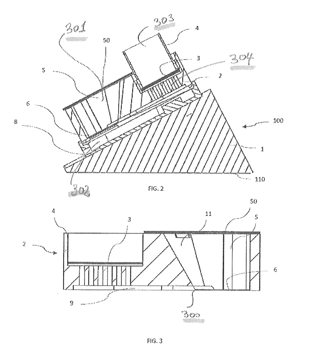
[0216]The advantage provided by the device described herein is by virtue of its geometry, in this case an incline of the filtering means of the collecting tank of 30°, which allows effective harvesting of the microorganisms by means of a liquid solution which finally results in a bacterial suspension.

[0217]The lysis-filtration protocol is the following:[0218]The filtration is carried out on a 0.2 μm PES filtration membrane used as filtering means of the collecting tank on the device according to the invention.[0219]The test sample is 0.8 ml of blood culture which is treated with 0.4 ml of 0.3 M CAPS buffer / 0.45% Brij for 2 minutes, followed by filtration for 2 minutes.[0220]3 washes with 175 μl of wash buffer 1 (0.45% NaCl / 0.005% Brij ...


PUM

PropertyMeasurementUnit
pore sizeaaaaaaaaaa
pore sizeaaaaaaaaaa
pore sizeaaaaaaaaaa

Abstract

A device for preparing biological samples including a fixed support of which the base extends in a first plane, a filtration block that can be removable, the filtration block including a collecting tank that itself includes a filtering device extending in a second plane and dividing the collecting tank into a collection area and a suction area, the suction area being designed to be connected to a suction device, the second plane of the filtering device being inclined relative to the plane of the base of the fixed support.

Description

BACKGROUND[0001]The field of the present invention is that of microbiological analysis. More particularly, the present invention relates to a device for preparing a biological sample with a view to a microbiological diagnosis.[0002]Vacuum filtration is conventionally used in laboratories. It is used in two ways:[0003]either to clarify a sample. The filtrate is then kept and the filter discarded,[0004]or to collect and concentrate particles or microorganisms of interest present in a liquid sample. In this second case, the filtrate is discarded, and the concentrate (also called retentate) and / or the filter are kept.[0005]A known device from the prior art is the Büchner funnel. Such a device is represented in FIG. 1. It comprises a funnel in which a perforated plate is transversely positioned. The funnel is fitted in a leaktight manner into the neck of a vacuum flask by means of a bung. The vacuum flask is connected to a suction source. A filter paper is placed on the perforated plate,...

Claims


Application Information

Patent Timeline
Patent Type & Authority Patents(United States)
IPC IPC(8): C12M1/26G01N1/40
CPCC12M33/04G01N1/40C12M33/14
Inventor BROYER, PATRICKVERON, LAURENTROSTAING, HERVE
Owner BIOMERIEUX SA
Why Eureka
Try Eureka