Insulated fiber reinforced door panel and method of making same

a technology of fiber reinforced door panels and fiber reinforced core materials, which is applied in the direction of doors/windows, door leaves, other domestic articles, etc., can solve the problems of affecting the lifecycle and cost of ownership of the product, the impact of the total weight of the door on the wear and tear of hardware, and the total weight of the door affects the freight and shipment costs of raw components, so as to improve structural integrity and reduce the effect of mass

Active Publication Date: 2018-12-11
AADG INC
View PDF23 Cites 3 Cited by
  • Summary
  • Abstract
  • Description
  • Claims
  • Application Information

AI Technical Summary

Benefits of technology

[0004]Bearing in mind the problems and deficiencies of the prior art, it is therefore an object of the present invention to provide a door panel that avoids the use of steel while improving structural integrity, is significantly lower in mass, is thermally efficient and provides an outer appearance free of weld marks.
[0006]It is a further object of the present invention to provide a door panel that eliminates the need for steel end channels used for locating steel or FRP reinforcements, thus reducing the weight of the door while reducing the thermal transfer of the door components.
[0007]Yet another object of the present invention is to provide an insulated door panel that employs stiffeners which are also corrosion resistant and provide dimensional stability to the panel under thermal loading.

Problems solved by technology

These core materials are very heavy and may also use heavy gage steel components to meet performance requirements and specifications.
As a result, the total weight of the door impacts hardware wear and tear, product lifecycle and cost of ownership.
These prior door components' weight and finished door opening total weight impacts freight and shipment costs of raw components, as well as finished goods shipment costs.
Steel is not dimensionally stable under thermal loading, and therefore negatively impacts the energy efficiency of the door opening thermal performance for preventing thermal transfer.
These steel components are also vulnerable to corrosion and rusting.

Method used


Image

  • Insulated fiber reinforced door panel and method of making same
  • Insulated fiber reinforced door panel and method of making same
  • Insulated fiber reinforced door panel and method of making same

Examples


Embodiment Construction

)

[0033]In describing the preferred embodiment of the present invention, reference will be made herein to FIGS. 1-12 of the drawings in which like numerals refer to like features of the invention. Reference will also be made to the general direction of orientation of the door panel 20 of the invention.

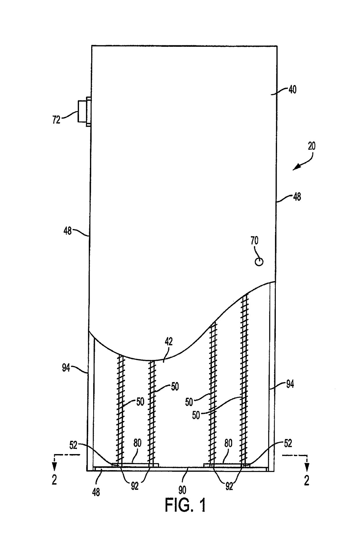
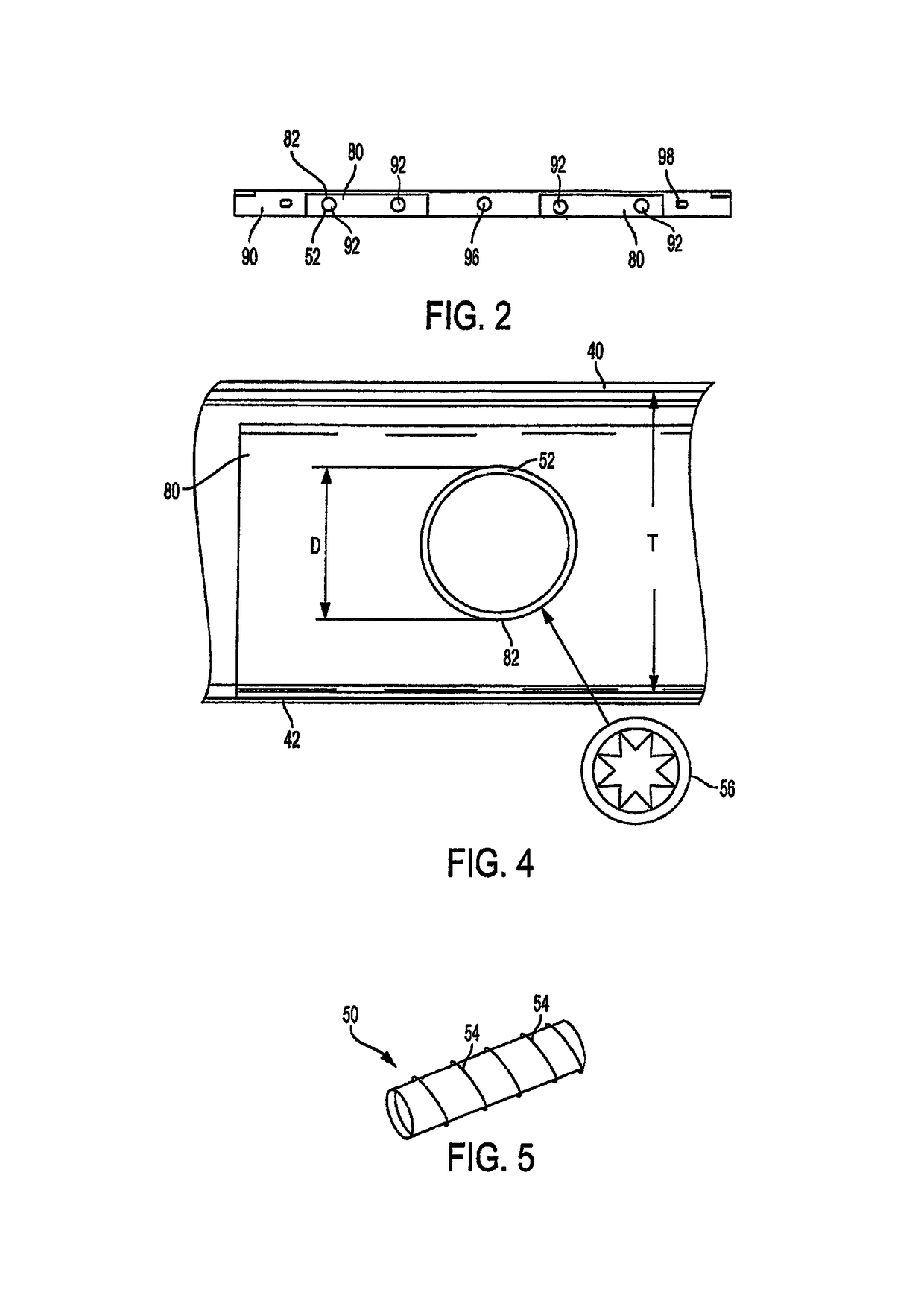
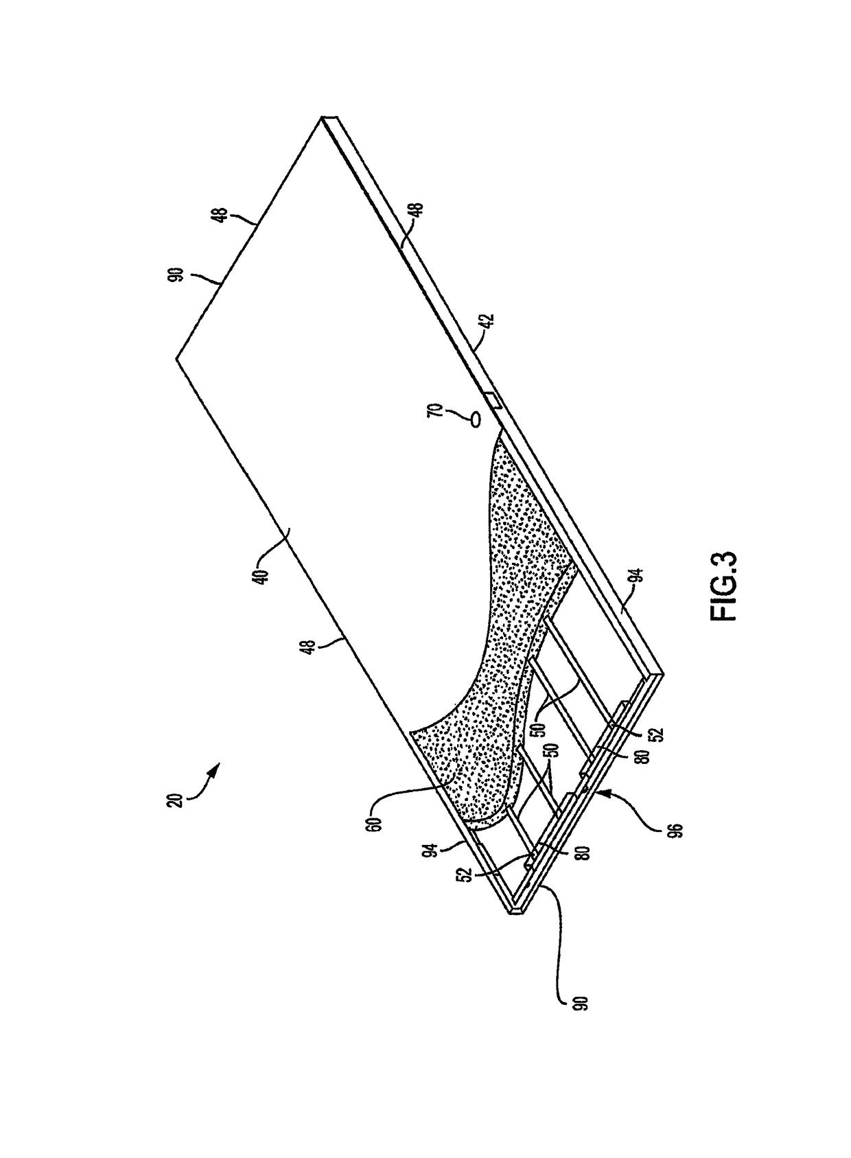
[0034]FIGS. 1, 2, 3, 4 and 5 show an embodiment of the insulated reinforced door panel 20 of the present invention. The door shell includes an inner panel 40 and a spaced outer panel 42 opposite the inner panel. The inner panel 40 and outer panel 42 form the exterior panels of the door, and may also be referred to as the door skin. The exterior panels may be made of any suitable sheet material, for example a metal or alloy such as about 14, 16, 18 or 20 gauge steel, a fiber reinforced plastic (FRP), wood, or composite. The exterior panels may be flat or embossed. The insulated door 20 includes door edges 48 extending between the periphery of the inner and outer panels. Upper and lower d...


PUM

PropertyMeasurementUnit
angleaaaaaaaaaa
lengthaaaaaaaaaa
thermally non-conductiveaaaaaaaaaa

Abstract

An insulated door panel comprises a shell having spaced first and second exterior panels and frame members adjacent edges of the panels, a plurality of stiffeners in a shell interior portion extending along a length or width of the panels, and a hardenable insulation material creating a bond between the exterior panels, stiffeners, and frame members in the shell interior portion. The stiffeners comprise a thermally non-conductive fiber reinforced polymer. The hardenable insulation fills substantially all of the space between the adjacent exterior panels, stiffeners, and frame members. The door panel also comprises end cap members composed of thermoplastic polycarbonate material, and has openings therein to receive the ends of the stiffeners.

Description

RELATED APPLICATIONS[0001]This application claims the benefit of U.S. Provisional Patent Application No. 62 / 376,673, filed Aug. 18, 2016 and U.S. Provisional Patent Application No. 62 / 400,297, filed Sep. 27, 2016.BACKGROUND OF THE INVENTION1. Field of the Invention[0002]The present invention relates to insulated door panels, and in particular, door panels having a cured-in-place internal structure for improving rigidity, thermal efficiency, aesthetics and manufacturability.2. Description of Related Art[0003]Typical Fiber Reinforced Plastic (FRP) door cores use polyurethanes as the standard core, and mineral core or fire resistant composite cores for fire rated FRP versions. These core materials are very heavy and may also use heavy gage steel components to meet performance requirements and specifications. As a result, the total weight of the door impacts hardware wear and tear, product lifecycle and cost of ownership. These prior door components' weight and finished door opening tot...

Claims


Application Information

Patent Timeline
Patent Type & Authority Patents(United States)
IPC IPC(8): E06B3/78E06B3/70B29C44/12E06B3/82B29C44/18B29K75/00B29K105/24B29K701/12B29L31/00B29L31/60
CPCE06B3/78B29C44/1228B29C44/18E06B3/7015E06B3/822B29K2075/00E06B2003/7051B29K2701/12B29K2995/0007B29K2995/0015B29L2031/608B29L2031/724E06B2003/7023B29K2105/24
Inventor GLOVER, DANIEL
Owner AADG INC
Why Eureka
Try Eureka