Discrete assemblers utilizing conventional motion systems

a motion system and assembler technology, applied in the direction of electric programme control, force/torque/work measurement apparatus, program control, etc., can solve the problems of limited plastics printing with a relatively narrow range of material properties, limited substrate material choice, and inability to match the properties and variety of electronic materials needed to print a full range of electronic devices. , to achieve the effect of more precise construction of objects

Inactive Publication Date: 2018-12-18
MASSACHUSETTS INST OF TECH
View PDF20 Cites 7 Cited by
  • Summary
  • Abstract
  • Description
  • Claims
  • Application Information

AI Technical Summary

Benefits of technology

[0011]An alternative approach to multi-material additive manufacturing looks to discretize material into individual building blocks. Digital materials are assemblies of individual building blocks, each having a discrete set of possible positions and orientations [see G. A. Popescu, T. Mahale, and N. A. Gershenfeld, “Digital materials for digital printing,” NIP Digit. Fabr. . . . , pp. 1-4, 2006]. The building blocks structurally interlock with neighboring ones such that they register to a lattice. This approach has many traits that make it a compelling alternative to conventional (analog) manufacturing techniques. For one, errors within a tolerance can be restored, enabling an assembler to assemble an object more accurate than itself. That is to say, two very different assemblers, if given the same building blocks, would assemble precisely the same object within the tolerance of the feature size of the building block. Secondly, since the building blocks structurally interlock, dissimilar materials are easily joined, enabling multi-material fabrication with a much broader range of materials. Finally, when the object is no longer needed, the parts can be disassembled and reused rather than thrown away.

Problems solved by technology

However, these printers are generally restricted to printing a single material at a time and only a small number of commercially available printers are able to simultaneously print with multiple materials; those that can, are limited to printing plastics with a relatively narrow range of material properties.
None of these printers, however, have been able match the properties and variety of electronic materials needed to print a full range of electronic devices.
Still, these formulations are one to two orders of magnitude less conductive than bulk metal and often require a post-bake processing step to evaporate the solvent, which limits the substrate material choice.
If the speed of the positioning is not precisely mapped to the rate of deposition or fusing of material, the fabricated object will have bumps or voids.

Method used


Image

  • Discrete assemblers utilizing conventional motion systems
  • Discrete assemblers utilizing conventional motion systems
  • Discrete assemblers utilizing conventional motion systems

Examples


Embodiment Construction

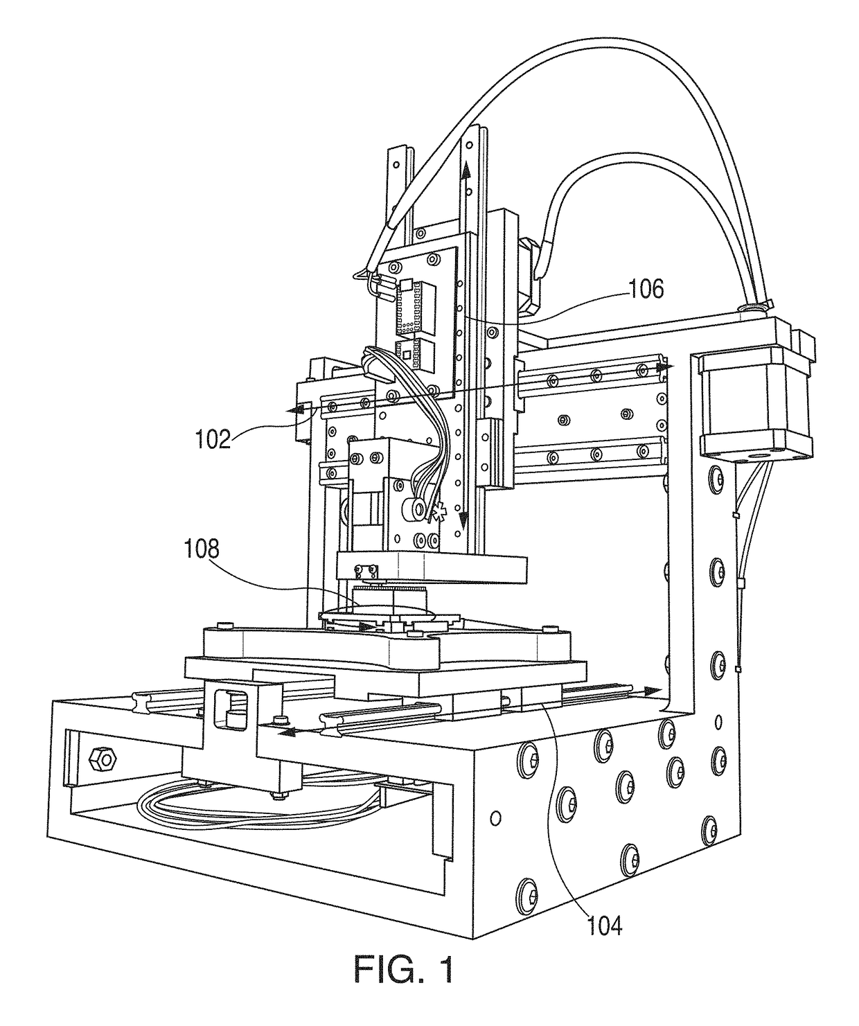
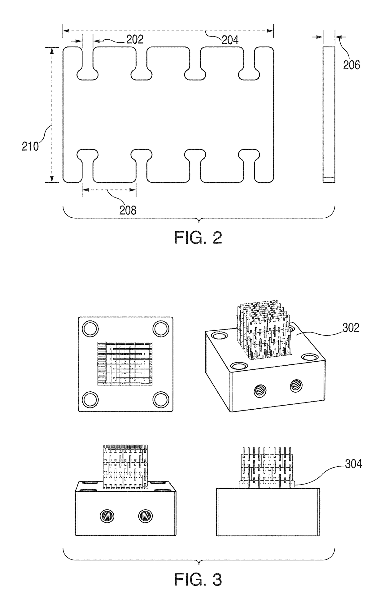
[0030]An embodiment of the present invention positions a toolhead relative to the structure being fabricated using three conventional linear axes: X 102, Y 104, and Z 106 (FIG. 1). A fourth C-axis (108) may be necessary if the part has a rotation asymmetry and requires a rotation about the Z-axis between layers (as is the case of the part pictured in FIG. 2 and structure pictured in FIG. 3). Conventional motion systems including, but not limited to, timing belts, leadscrews, and rack and pinion mechanisms may be used as power transmission between the motors and the positioning stages. The dimensions of FIG. 2 (in inches) are 0.010 202, 0.1950 204, 0.010 206, 0.05 208, and 0.1250 210. FIG. 3 shows a discretely assembled structure 302 and a substrate 304.

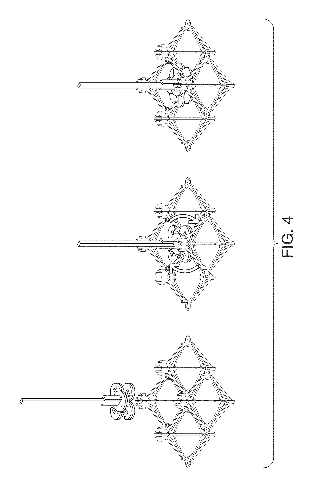
[0031]Another embodiment of the present invention positions a toolhead relative to a lattice structure along three conventional linear axes of motion (X, Y, and Z), and also includes a foot mechanisms for moving the machine relative t...


PUM

PropertyMeasurementUnit
speedaaaaaaaaaa
thicknessaaaaaaaaaa
conductanceaaaaaaaaaa

Abstract

An alternative to additive manufacturing is disclosed, introducing an end-to-end workflow in which discrete building blocks are reversibly joined to produce assemblies called digital materials. Described is the design of the bulk-material building blocks and the devices that are assembled from them. Detailed is the design and implementation of an automated assembler, which takes advantage of the digital material structure to avoid positioning errors within a large tolerance. To generate assembly sequences, a novel CAD / CAM workflow is described for designing, simulating, and assembling digital materials. The structures assembled using this process have been evaluated, showing that the joints perform well under varying conditions and that the assembled structures are functionally precise.

Description

[0001]This invention was made with Government support under Grant No. CMMI-1344222 awarded by the National Science Foundation, Grant Nos. NNX14AG47A, NNX14AM40H, and NNX14AH75A awarded by NASA, and Grant No. W911NF-14-2-0063 awarded by the Army Research Office. The Government has certain rights in the invention.[0002]This application claims the benefit of U.S. Provisional Application No. 62 / 151,709, filed Apr. 23, 2015, the entire disclosure of which is herein incorporated by reference.TECHNICAL FIELD OF THE INVENTION[0003]The present invention relates to electronic digital materials, and more specifically to automated assembly of electronic digital materials.BACKGROUND OF THE INVENTION[0004]Prior work has been done in making machines that assemble structures from discrete parts. Hiller et al. showed a method of parallel part placement of voxel spheres in [J. Hiller and H. Lipson, “Methods of Parallel Voxel Manipulation for 3D Digital Printing,” in Proceedings of the 18th solid free...

Claims


Application Information

Patent Timeline
Patent Type & Authority Patents(United States)
IPC IPC(8): G05B19/418B25J9/16B23P19/04B33Y30/00G05B19/402G01L5/00B25J5/02B33Y10/00B29C64/00G06F17/50
CPCB25J9/1687B23P19/04B25J5/02B29C64/00B33Y10/00G01L5/0085G05B19/402B33Y30/00Y10S901/09G05B2219/45064G05B2219/49023G06F17/50G06F30/00
Inventor LANGFORD, WILLIAM KAICARNEY, MATTHEW ELIJENETT, BENJAMINGERSHENFELD, NEIL
Owner MASSACHUSETTS INST OF TECH
Why Eureka
Try Eureka