
System and method for generating a lithographic image with the use of a reflective concave curvilinear surface and a digital hologram in a diverging beam

a technology of concave curvilinear surface and reflected beam, which is applied in the field of microlithography, can solve the problems of unsolved diffraction angle problems of high-aperture beams, cannot be achieved with flat mirrors, etc., and achieves the effects of shortening production time, optimizing manufacturing process, and eliminating aberration

Active Publication Date: 2018-12-25
RAKHOVSKY VADIM
View PDF8 Cites 1 Cited by
  • Summary
  • Abstract
  • Description
  • Claims
  • Application Information

AI Technical Summary

Benefits of technology

The patent text discusses the use of digital holograms and the advantages of using an elliptical reflective surface or an SLM for producing beams with low aberration errors. The use of an SLM makes it possible to shorten production time and optimize manufacturing process. The technical effects of the patent text are to provide a more efficient and cost-effective way to produce high-quality beams with low aberration errors.

Problems solved by technology

This is because in the case of high-aperture beams it is necessary to convert a diverging beam into a converging one, which cannot be achieved with a flat mirror.
In fact, a flat mirror surface can be made but the problem associated with diffraction angles of high-aperture beams will remain unsolved.

Method used


Image

  • System and method for generating a lithographic image with the use of a reflective concave curvilinear surface and a digital hologram in a diverging beam
  • System and method for generating a lithographic image with the use of a reflective concave curvilinear surface and a digital hologram in a diverging beam
  • System and method for generating a lithographic image with the use of a reflective concave curvilinear surface and a digital hologram in a diverging beam

Examples


Embodiment Construction

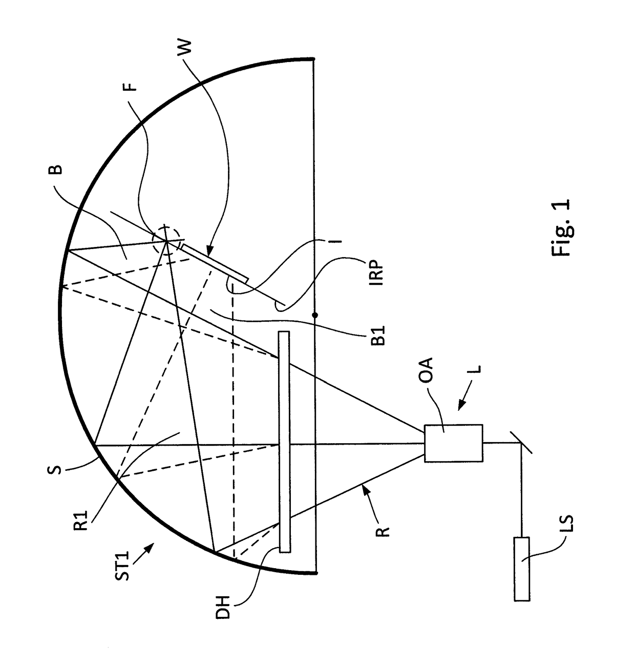
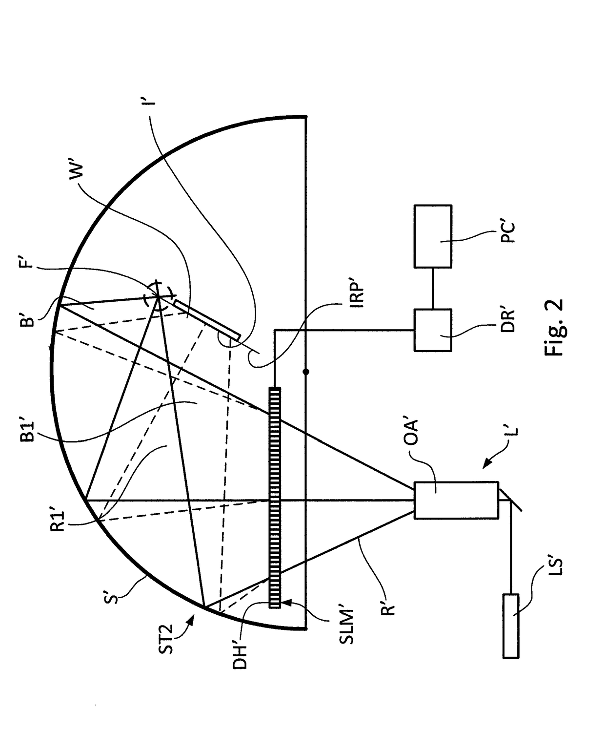
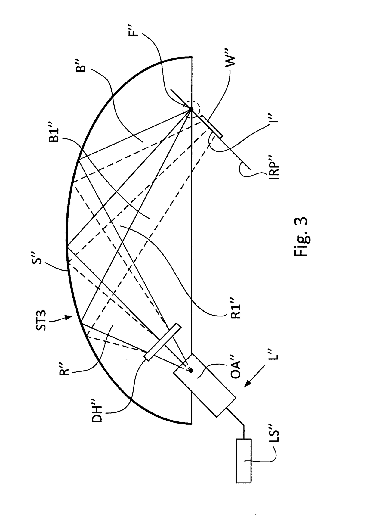
[0018]The present invention relates to the semiconductor industry, in particular, to microlithography, and more specifically to a system and method of forming a lithographic image with the use of digital holograms and an optical system that contains semispherical, semielliptical surfaces, or other concave curvilinear second-order surfaces of bodies of revolution. For simplicity of the description such holographic image formation systems with reflective concave curvilinear surfaces will be further referred to merely as “holographic image formation systems”. More specifically, the above systems and methods are based on the use of digital holograms in combination with partially spherical or semielliptical surfaces.

System with Semispherical Reflective Surface and Stationary DH

[0019]The main principle of the invention will be better understood with reference to FIG. 1, which is a schematic view of the holographic image formation system ST1 for forming a lithographic image with the use of...


PUM

PropertyMeasurementUnit
coherence lengthaaaaaaaaaa
chemical propertiesaaaaaaaaaa
sub-wavelength sizeaaaaaaaaaa

Abstract

A system for generating a lithographic image contains a light source that emits a diverging light beam and a reflective concave curvilinear surface onto which the diverging light beam falls and which reflects the diverging beam in the form of a converging beam. A digital hologram, which is placed into a diverging beam between the light source and the reflective surface, is coded in accordance with the lithographic image either preliminarily or dynamically, with the use of a spatial light modulator. From the curvilinear surface the spatially modulated beam is reflected in the form of a converging beam which falls onto an image-receiving substrate that is located in the image restoration plane and on which the lithographic image is generated.

Description

FIELD OF THE INVENTION[0001]The present invention relates to the semiconductor industry, in particular, to microlithography, and more specifically to a system and method for generating a lithographic image with the use of a reflective concave curvilinear surface and a digital hologram in a converging reflected beam. More specifically, the above method is based on the use of a stationary digital hologram or a dynamically controlled digital hologram placed in a diverging light beam supplied from the light source in combination with a spherical, semielliptical, or another reflective concave curvilinear second-order surface of a body of revolution.DESCRIPTION OF THE RELATED ART[0002]Lithography and, in particular, photolithography is a well-known technique in semiconductor and printed circuit board (PCB) manufacture for creating electrical components and circuits. Photolithography involves placing a mask in front of a substrate, which has been covered by a layer of photoresist, before e...

Claims


Application Information

Patent Timeline
Patent Type & Authority Patents(United States)
IPC IPC(8): G03H1/08G03H1/22G03H1/00G03F7/20G02B5/32G03H1/04
CPCG03H1/0005G03F7/702G03F7/70233G03F7/70408G03H1/0486G03H1/0891G03H1/2205G03H1/2294G02B5/32G03H2226/02G03H2001/0094G03H2001/221G03H2222/23G03H2222/52G03H2223/24
Inventor RAKHOVSKY, VADIMBORISOV, MIKHAILSHAMAEV, ALEKSEYCHELYUBEEV, DMITRYCHERNIK, VITALYMIKHEEV, PETER
Owner RAKHOVSKY VADIM
Learn More