Eureka AIR delivers breakthrough ideas for toughest innovation challenges, trusted by R&D personnel around the world.

Hybrid amplifier and signal combiner

a signal combiner and hybrid technology, applied in the field of radio frequency signal processing, can solve problems such as affecting system performance and generating undesirable distortion

Active Publication Date: 2018-12-25
SKYWORKS SOLUTIONS INC
View PDF8 Cites 3 Cited by
  • Summary
  • Abstract
  • Description
  • Claims
  • Application Information

AI Technical Summary

Problems solved by technology

Certain amplifier devices can generate undesirable distortion, which may affect system performance.

Method used


Image

  • Hybrid amplifier and signal combiner
  • Hybrid amplifier and signal combiner
  • Hybrid amplifier and signal combiner

Examples


Embodiment Construction

[0021]The headings provided herein, if any, are for convenience only and do not necessarily affect the scope or meaning of the claimed invention.

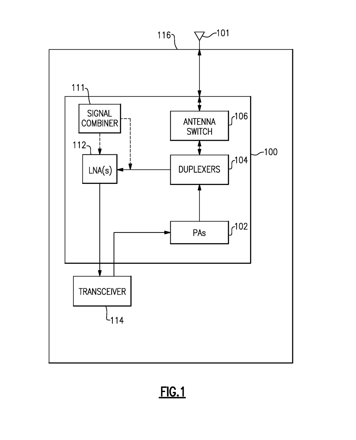
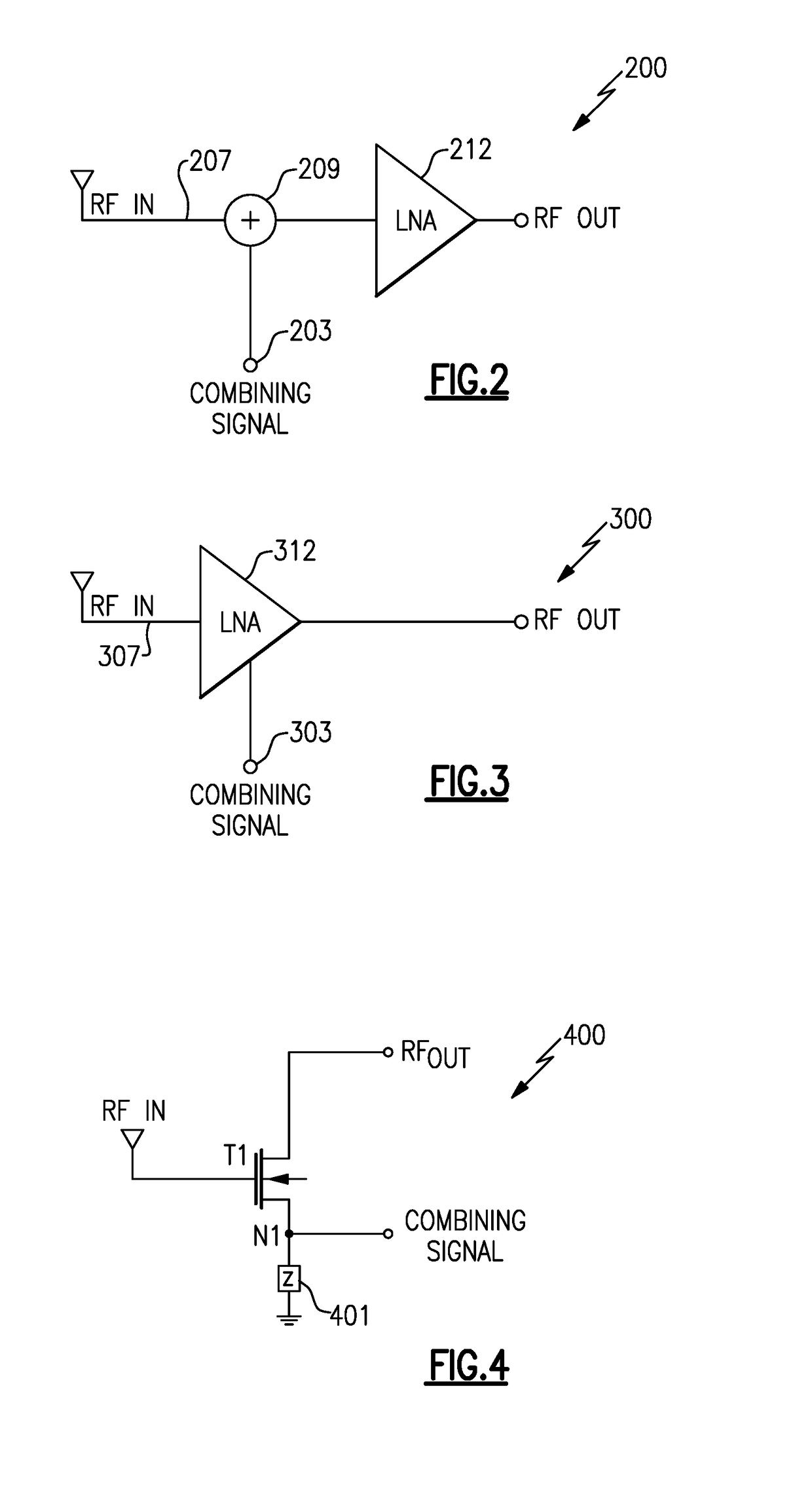
[0022]FIG. 1 shows a radio-frequency (RF) system, including RF circuitry and / or modules, implemented on a circuit board 116 according to one or more embodiments. The system includes one or more low-noise amplifiers (LNAs) 112 configured to amplify a signal of interest received by the system over, for example, one or more antennas 101. The system may further include a signal combiner module or circuitry 111 configured to combine a noise cancelling signal in the received signal path to at least partially eliminate noise in the signal, such as noise generated by one or more other modules or devices of the system. Certain embodiments disclosed herein provide for combined LNA and signal combiner circuitry, which may provide certain benefits, as described in greater detail below.

[0023]FIG. 1 includes a radio-frequency (RF) module 100 including on...


PUM


Abstract

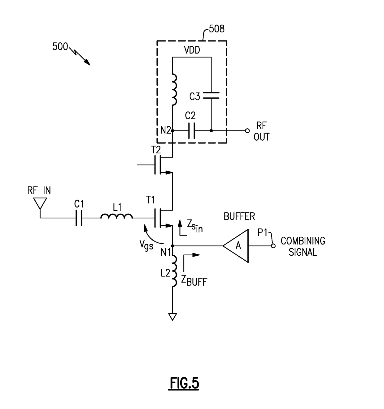
A radio-frequency module comprises a low-noise amplifier including a common source transistor having a gate node that receives a radio-frequency input signal and a drain node that transmits a combined radio-frequency output signal, and a correction signal input path configured to receive a correction signal and provide the correction signal to a source node of the common source transistor to generate, at least in part, the combined radio-frequency output signal.

Description

CROSS-REFERENCE TO RELATED APPLICATION(S)[0001]This application claims priority to U.S. Provisional Application No. 62 / 242,955, filed Oct. 16, 2015, and entitled HYBRID AMPLIFIER AND SIGNAL COMBINER, the disclosure of which is hereby incorporated by reference in its entirety.BACKGROUNDField[0002]The present disclosure relates to radio frequency signal processing.Description of the Related Art[0003]Amplifier devices can be used in processing radio frequency signals. Certain amplifier devices can generate undesirable distortion, which may affect system performance.SUMMARY[0004]In accordance with a number of implementations, the present disclosure relates to a radio-frequency module comprising a low-noise amplifier including a common source transistor having a gate node that receives a radio-frequency input signal and a drain node that transmits a combined radio-frequency output signal, and a correction signal input path configured to receive a correction signal and provide the correct...

Claims


Application Information

Patent Timeline
Patent Type & Authority Patents(United States)
IPC IPC(8): H03F3/193H04B1/04H03F3/21H03F1/22H03F1/32H03F3/24
CPCH03F3/245H04B1/0475H03F1/223H03F1/3205H03F3/193H03F3/211H03F2200/111H03F2200/294H03F2200/333H03F2200/451H03F2200/75H04B2001/0408H03F3/24
Inventor COOK, MACKENZIE BRIANROGERS, JOHN WILLIAM MITCHELL
Owner SKYWORKS SOLUTIONS INC
Why Eureka
Eureka Blog
Learn More