Wearable infrared temperature sensing device

a temperature sensing device and infrared technology, applied in the field of wearable devices, can solve problems such as reducing detection accuracy, and achieve the effect of increasing detection accuracy and blocking noise generated

Active Publication Date: 2019-01-01
PIXART IMAGING INC
View PDF12 Cites 5 Cited by
  • Summary
  • Abstract
  • Description
  • Claims
  • Application Information

AI Technical Summary

Benefits of technology

[0008]The instant disclosure addresses the technical problem of providing a wearable device which includes a far infrared temperature sensing device containing a metal shielding structure to block the noise generated from other sensors and external electronic products, and to block other far infrared from passing into the case of the wearable device avoiding interference with the sensing device, so as to increase the detection accuracy on the far infrared temperature.
[0013]This instant disclosure has the benefit that the metal shielding structure surrounding the internal sensing elements (e.g., sensor chip, circuit substrate) in the far infrared temperature sensing device of the wearable device can block the noise generated from other sensors and external electronic products that can interfere with the sensing elements, and blocks other far infrared from passing into the case of the wearable device avoiding the sensing result of the sensor chip from being affected, so as to increase the detection accuracy on the far infrared temperature. The metal shielding structure further has an opening, which only allows the infrared at a certain position to enter, and other parts outside the opening are blocked by the metal shielding structure and cannot enter into the wearable device. In this way, it can have a superior Signal-to-Noise Ratio (SNR). Meanwhile, the detection accuracy on the far infrared temperature can be increased.

Problems solved by technology

Furthermore there are external electronic signals, such that the internal and external signals interfere with each other, so as to decrease the detection accuracy.
Therefore, solving the problem of noise signals generated among the various sensors and the external electronic products is one of the important issues in the art.

Method used


Image

  • Wearable infrared temperature sensing device
  • Wearable infrared temperature sensing device
  • Wearable infrared temperature sensing device

Examples


second embodiment

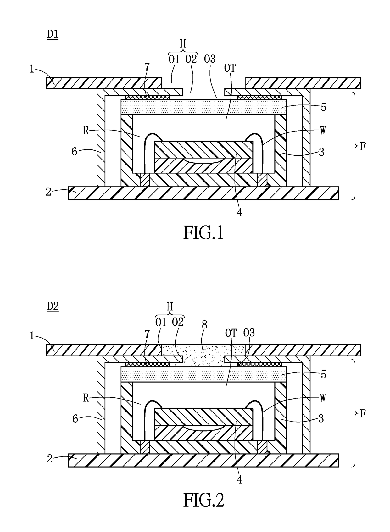
[0042]Please refer to FIG. 2. FIG. 2 shows a schematic view of a wearable device D2 of a second embodiment in the instant disclosure. The wearable device D2 of the second embodiment of this instant disclosure has a similar package structure to the wearable device D1 of the first embodiment of this instant disclosure, and the similar elements refer to the above description. The difference between the wearable device D2 of the second embodiment and the wearable device D1 of the first embodiment in this instant disclosure is that, the wearable device D2 of the second embodiment in this instant disclosure further includes an infrared passing glue 8 which is used to fill the through hole H and the third opening O3, and is used to filter out the non-infrared light.

[0043]In the second embodiment of this instant disclosure, the through hole H formed by the first opening O1 of the case 1, the second opening O2 of the metal shielding structure 6, and the third opening O3 of the waterproof str...

third embodiment

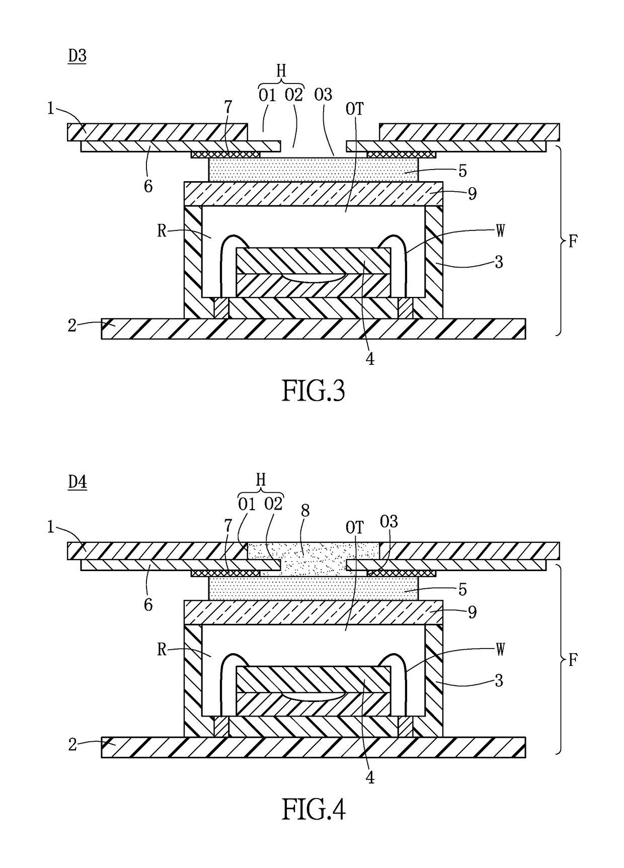
[0044]Please refer to FIG. 3. FIG. 3 shows a schematic view of a wearable device D3 of a third embodiment in the instant disclosure. The wearable device D3 of the third embodiment of this instant disclosure has similar package structure with the wearable device D1 of the first embodiment of this instant disclosure, and for similar elements refer to the above description, identical numerals are used throughout the specification and figures that represent identical structure have identical application, function, and are selected from identical materials.

[0045]The difference between the wearable device D3 of the third embodiment and the wearable device D1 of the first embodiment in this instant disclosure is that, the wearable device D3 of the third embodiment in this instant disclosure further includes an infrared passing structure 9 which is disposed at the top opening OT of the assembly structure 3 to enclose the accommodating space R of the assembly structure 3, and the filter stru...

fourth embodiment

[0047]Please refer to FIG. 4. FIG. 4 shows a schematic view of a wearable device D4 of a fourth embodiment in the instant disclosure. The wearable device D4 of the fourth embodiment of this instant disclosure has similar package structure with the wearable device D3 of the third embodiment of this instant disclosure.

[0048]The difference between the wearable device D4 of the fourth embodiment and the wearable device D3 of the third embodiment in this instant disclosure is that, the wearable device D4 of the fourth embodiment in this instant disclosure further includes an infrared passing glue 8 which is used to fill the through hole H and the third opening O3 to enclose the through hole H and the third opening O3.

[0049]In the fourth embodiment of this instant disclosure, the through hole H formed by the first opening O1 of the case 1 and the second opening O2 of the metal shielding structure 6, and the third opening O3 of the waterproof structure 7 are filled by the infrared passing ...


PUM


Abstract

A wearable device includes a case and a far infrared temperature sensing device. The case has a first opening. The far infrared temperature sensing device is disposed inside the case of the wearable device. The far infrared temperature sensing device includes an assembly structure, a sensor chip, a filter structure, and a metal shielding structure. The assembly structure has an accommodating space and a top opening. The sensor chip is disposed in the accommodating space of the assembly structure. The filter structure is disposed above the sensor chip. The metal shielding structure is disposed above the sensor chip, and has a second opening to expose the filter structure. The first and second openings are communicated to cooperatively define a through hole.

Description

CROSS REFERENCE TO RELATED APPLICATION[0001]This is a continuation-in-part application of U.S. application Ser. No. 14 / 726,472, filed on 30 May 2015 and entitled “WEARABLE DEVICE WITH COMBINED SENSING CAPABILITIES”, now pending, the entire disclosures of which are incorporated herein by reference.BACKGROUND OF THE INVENTION[0002]1. Field of the Invention[0003]The instant disclosure relates to a wearable device; in particular, to a wearable infrared temperature sensing device.[0004]2. Description of Related Art[0005]Using exercise to maintain health has become increasingly popular, and the development of related products for self-monitoring of physiological status are more important, such as wearable or handheld consumer electronic products, for example, fitness bracelets, smartwatches, and smartphones. These products include biomarkers for measuring heart beats, blood pressure, blood sugar, or blood oxygen levels, or for monitoring sleep quality. Smartwatches are the most popular we...

Claims


Application Information

Patent Timeline
Patent Type & Authority Patents(United States)
IPC IPC(8): G01J5/02H04N5/225G01J5/06H04N5/33G01J5/04B81B7/00
CPCG01J5/0265B81B7/0064B81B7/0067G01J5/041G01J5/06H04N5/2257H04N5/33G01J5/045B81B2201/0278H04N23/57
Inventor SUN, CHIH-MINGTSAI, MING-HANTSAI, CHENG-NAN
Owner PIXART IMAGING INC
Why Eureka
Try Eureka