Laminated iron core and manufacturing method of laminated iron core

a technology of laminated iron and core, which is applied in the direction of dynamo-electric machines, magnetic circuit shapes/forms/construction, fastening means, etc., can solve the problems of poor assembly of the motor, noise or vibration at the time of driving, distortion (warp) etc., to prevent a crack in the coupling resin, improve productivity, and increase the distortion in the iron core pi

Active Publication Date: 2019-01-01
MITSUI HIGH TEC INC
View PDF16 Cites 0 Cited by
  • Summary
  • Abstract
  • Description
  • Claims
  • Application Information

AI Technical Summary

Benefits of technology

[0011]In addition, there is a method for simultaneously blanking plural iron core pieces with plural strip materials stacked for the purpose of improving productivity, but in this case, the distortion in the iron core piece tends to be more increased.
[0012]The present invention has been implemented in view of such circumstances, and a non-limited object of one or more aspects of the present invention is to provide a laminated iron core capable of preventing a crack in a coupling resin resulting from a distortion in an iron core piece, and a manufacturing method of the laminated iron core.

Problems solved by technology

However, thinning of the strip material tends to increase a distortion (warp) in the strip material, with the result that a distortion (warp) in the iron core piece blanked from the strip material is also increased.
As a result, problems such as poor assembly of the motor, breakage, noise or vibration at the time of driving arise.
In addition, there is a method for simultaneously blanking plural iron core pieces with plural strip materials stacked for the purpose of improving productivity, but in this case, the distortion in the iron core piece tends to be more increased.

Method used


Image

  • Laminated iron core and manufacturing method of laminated iron core
  • Laminated iron core and manufacturing method of laminated iron core
  • Laminated iron core and manufacturing method of laminated iron core

Examples


examples

[0069]Next, Examples performed in order to check the action and effect of the present invention will be described.

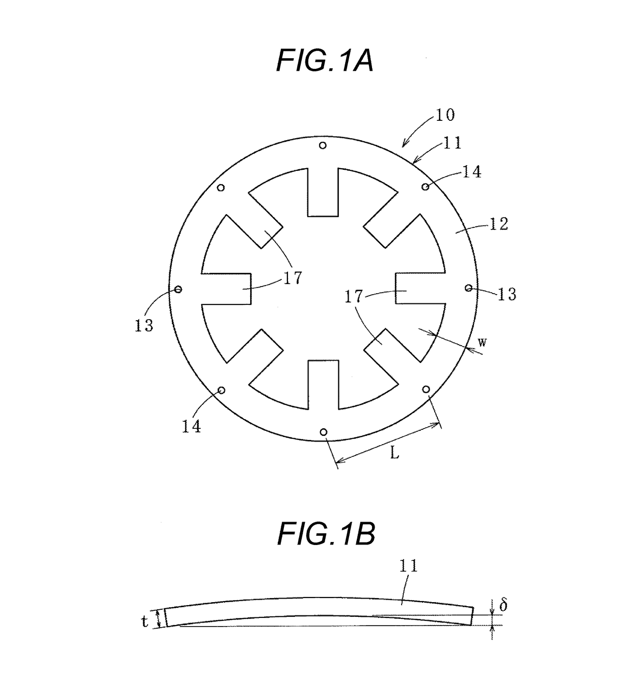
[0070]Outline specifications of a product (stator laminated iron core) used are described below.

[0071]Outside diameter: ϕ223 mm

[0072]Distance L between through holes: 50 mm

[0073]Width w of yoke: 30 mm

[0074]Lamination thickness of laminated iron core: 50 mm

[0075]Young's modulus E of strip material: 180 GPa (180000 N / mm2)

[0076]In this laminated iron core, the safety factor η was set at 2, and various conditions of the plate thickness t of the iron core piece, the number of iron core pieces blanked simultaneously (the number of simultaneously blanked pieces), the cross-sectional area S of each of the through holes and the strength T of the resin were changed, and the withstand load F of the resin and the reaction force W of the iron core piece were calculated, and it was examined whether or not the resin was cracked.

[0077]Table 1 shows results and the various conditions des...


PUM

PropertyMeasurementUnit
thicknessaaaaaaaaaa
thicknessaaaaaaaaaa
thicknessaaaaaaaaaa

Abstract

A laminated iron core includes laminated iron core pieces, in which coupling parts are formed so as to communicate in a lamination direction of the laminated iron core pieces, and the coupling parts are filled with resins. The laminated iron core satisfies the following formula: (T×S) / η>{(4×E×δ×w×t3) / L3}×n, where T is a strength (N / mm2) of the resin; S is a cross-sectional area (mm2) of the coupling part or the resin; E is a Young's modulus (N / mm2) of the strip material; δ is a distortion amount (mm) of the iron core piece; w is a width (mm) of the iron core piece in a radial direction; t is a plate thickness (mm) of the iron core piece; n is the number of laminated iron core pieces; L is a distance (mm) between the coupling parts adjacent in the circumferential direction; and η is a safety factor.

Description

CROSS REFERENCE TO RELATED APPLICATION(S)[0001]This application is based upon and claims the benefit of priority of Japanese Patent Application No. 2014-204787 filed on Oct. 3, 2014, the contents of which are incorporated herein by reference in its entirety.BACKGROUND OF THE INVENTION[0002]1. Field of the Invention[0003]The present invention relates to a laminated iron core in which iron core pieces adjacent in a lamination direction are mutually coupled using a resin, and a manufacturing method of the laminated iron core.[0004]2. Description of the Related Art[0005]In manufacture of a laminated iron core, generally, iron core pieces adjacent in a lamination direction are mutually bonded using caulking or welding from the standpoint of cost or ease of manufacture, but there are problems of, for example, a decrease in an occupancy rate of area or an increase in iron loss due to a short circuit between the iron core pieces.[0006]Hence, a method for mutually bonding iron core pieces by...

Claims


Application Information

Patent Timeline
Patent Type & Authority Patents(United States)
IPC IPC(8): H02K1/06H02K15/12H02K15/02B29C70/84F16B11/00B29L9/00
CPCH02K15/02B29C70/845H02K15/12F16B11/006H02K1/06B29L2009/003
Inventor HASUO, YUSUKEODAHARA, TOYOSHI
Owner MITSUI HIGH TEC INC
Why Eureka
Try Eureka