Input and output device with frame

a technology of input and output device and frame, which is applied in the direction of television system, electric apparatus casing/cabinet/drawer, instruments, etc., can solve the problems of high material loss, increased manufacturing cost, time-consuming and inefficient manufacturing, etc., and achieves the effect of simplifying the automatic, mechanical production of the frame and improving the exterior appearance of the fram

Active Publication Date: 2019-01-08
B&R IND AUTOMATION GMBH
View PDF31 Cites 1 Cited by
  • Summary
  • Abstract
  • Description
  • Claims
  • Application Information

AI Technical Summary

Benefits of technology

[0017]The external appearance of the frame can be improved if at least two frame sections adjoining each other are mitred or dovetailed for forming the connecting surfaces at a corner of the frame. In addition, such connecting surfaces also simplify the automated, mechanical production of a frame.
[0018]For hygiene reasons, it is advantageous for any joining material which protrudes after joining to be removed from the external front face and / or the external peripheral surface through finishing. As a result, no dirt can accumulate there. The same effect can be achieved if a cover sheet which covers at least the bonding layer is glued over the external front face and / or the external peripheral surface, or the external front face and / or the external peripheral surface is painted or coated at least in the area of the bonding layer.

Problems solved by technology

Naturally, this results in very high material losses, which increases the costs for such display frames and also makes manufacturing time-consuming and inefficient.
In principle, such one-piece display frames could also be manufactured using die casting or injection moulding processes, but there is little prospect for this owing to the high tooling costs (e.g. for dies) as a result of the low production volumes.
It is obvious that such a frame cannot be sealed at the corners at which the bent sides adjoin each other.
Such a frame is therefore unsuitable for an industrial application.
The frame has a recess at the corners, meaning that the frame is not sealed and is therefore not suitable for industrial use.

Method used


Image

  • Input and output device with frame
  • Input and output device with frame

Examples


Embodiment Construction

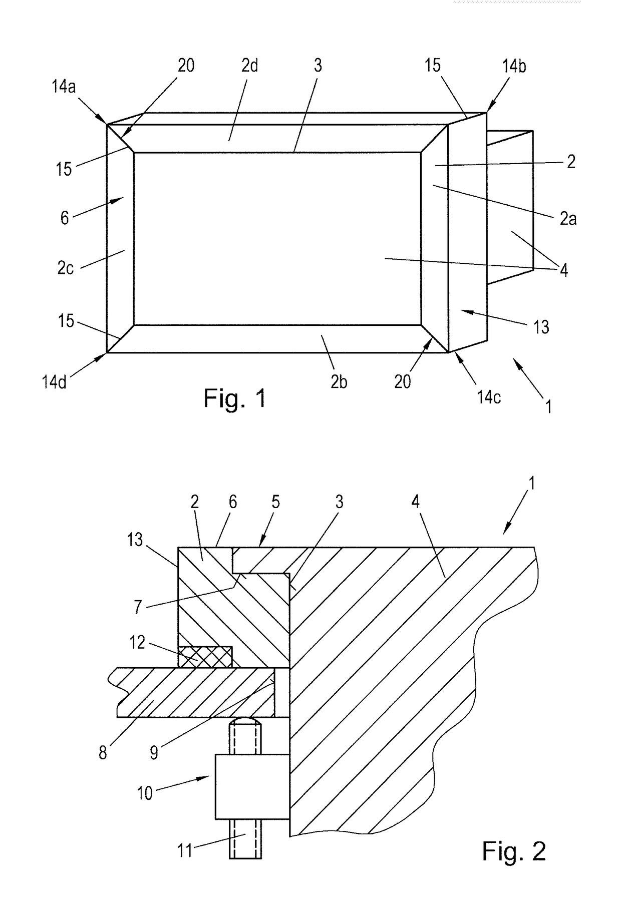
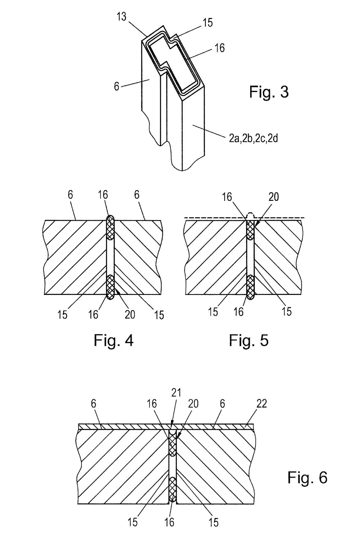
[0013]Embodiments of the present invention produce an input and output device for industrial use as cost-effectively as possible, which device also fulfils the above-specified requirements in an industrial environment.

[0014]In embodiments of the invention, the frame is assembled from a plurality of individual frame sections which are connected with one another at the corners in order to form the frame and are firmly bonded (substance-to-substance joint) at the connecting surfaces in order to form a fully enclosed front face of the frame and a fully enclosed external peripheral (circumferential) surface of the frame. Since a wide variety of profiles in a wide variety of embodiments are used for a wide variety of areas of application, these are widely available and appropriately cost-effective. Since hardly any waste and / or scrap is produced by the usual methods of production of the profiles, regardless of their material, an additional cost advantage applies. Thanks to the frame which...


PUM


Abstract

In order to manufacture an input and output device industrial use as cost-effectively as possible, while also fulfilling the demanding requirements in an industrial environment, it is provided that the frame of the input and output device is assembled from a plurality of individual frame sections which are connected to one another at the corners in order to form the frame and which are firmly bonded at the adjoining connecting surfaces in order to form a fully sealed external front face of the frame and a fully sealed external peripheral surface of the frame.

Description

CROSS-REFERENCE TO RELATED APPLICATIONS[0001]The present application is a U.S. National Stage of International Patent Application No. PCT / EP2015 / 063336 filed Jun. 15, 2015, and claims priority under 35 U.S.C. § 119 and 365 of Austria Patent Application No. A 50426 / 2014 filed Jun. 18, 2014. Moreover, the disclosure of International Patent Application No. PCT / EP2015 / 063336 is expressly incorporated by reference herein in its entirety.BACKGROUND OF THE INVENTION1. Field of the Invention[0002]The subject of the invention relates to an input and output device for industrial use with a frame which is sealed around the periphery (circumference) with a continuous central recess in which an input / output unit is set in, and a method for the manufacturing of such a frame and input and output device.2. Discussion of Background Information[0003]A majority of modern input and output devices as man-machine interfaces are based on display or touch screen technology as input and output units. Button...

Claims


Application Information

Patent Timeline
Patent Type & Authority Patents(United States)
IPC IPC(8): H05K5/02G06F3/041H05K5/00H05K7/00G06F1/16H05K7/14H05K7/18H04N5/64
CPCH05K7/14G06F1/1601G06F1/1656H05K7/18H04N5/64H05K5/0017H05K7/00G06F3/041G02F1/13G02F1/1333G06F3/00H05K5/00H05K5/0217H05K5/04
Inventor ESTERBAUER, HERMANNWIMMER, JOHANN
Owner B&R IND AUTOMATION GMBH
Why Eureka
Try Eureka