
Combined cycle power plant

a technology of combined cycle and power plant, which is applied in the direction of machines/engines, mechanical energy handling, mechanical apparatus, etc., can solve the problems of increasing complexity and outweighing disadvantage, and achieve the effect of minimizing pressure drop and minimizing distan

Active Publication Date: 2019-01-15
GENERAL ELECTRIC TECH GMBH
View PDF6 Cites 1 Cited by
  • Summary
  • Abstract
  • Description
  • Claims
  • Application Information

AI Technical Summary

Benefits of technology

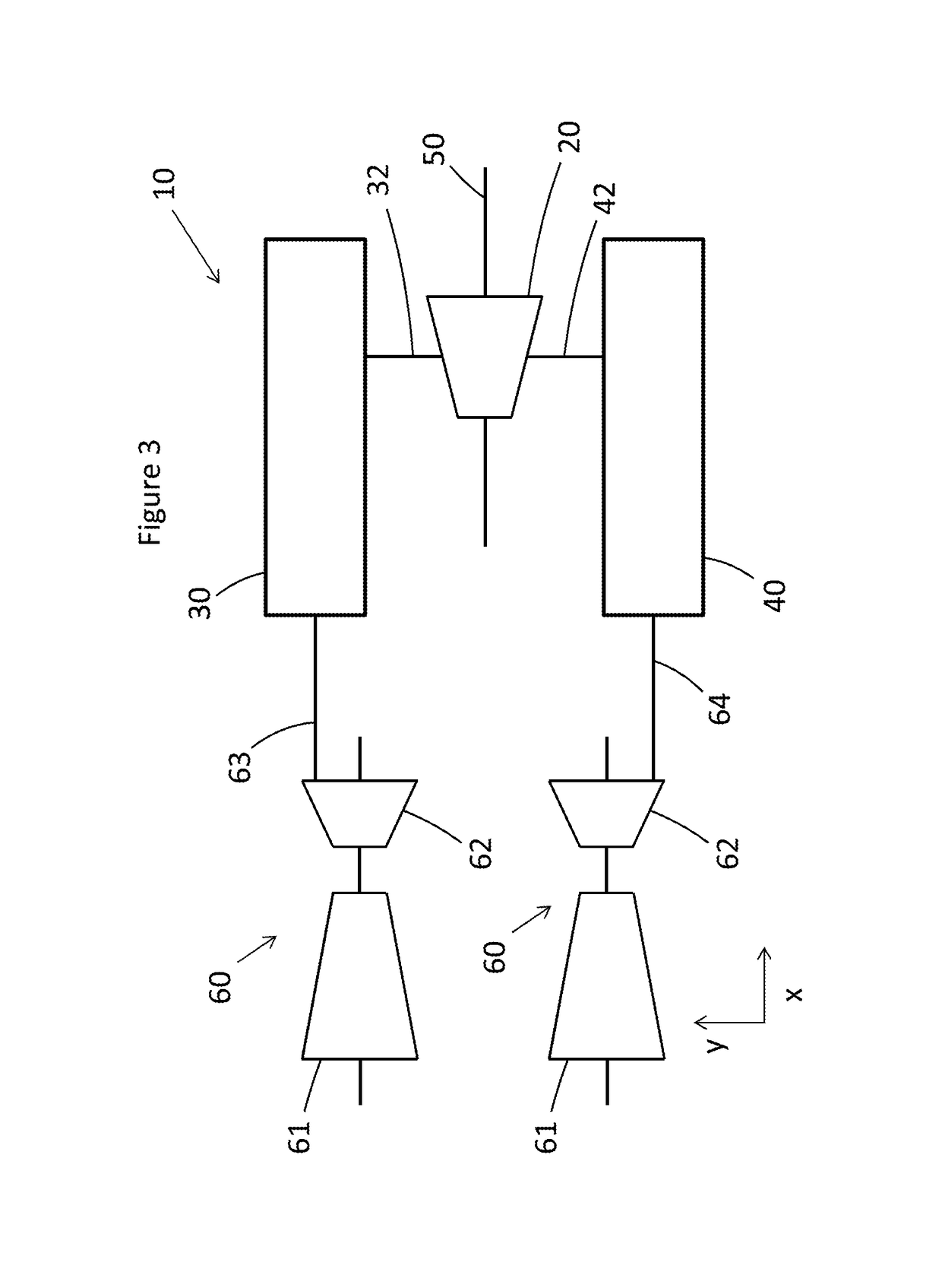
The invention provides a new layout for a combined cycle power plant that optimizes the arrangement of systems and equipment, reducing footprint, eliminating building structures, reducing duplicate systems and structures, reducing civil works and activities, and providing additional space for maintenance. The layout also simplifies the procurement and installation process, reduces part stress, reduces pressure drops, and reduces the quantity of steam pipes required. In particular, the invention includes a first steam turbine and a second steam turbine operating at lower pressure, which reduces the distance travelled by steam between the heat recovery steam generators and the steam turbines, minimizing pressure drops.

Problems solved by technology

Although the requirement for two mirrored designs for some units and components increases complexity, it has been appreciated that this disadvantage can be outweighed by the various benefits described elsewhere in the application.

Method used


Image

  • Combined cycle power plant
  • Combined cycle power plant
  • Combined cycle power plant

Examples


Embodiment Construction

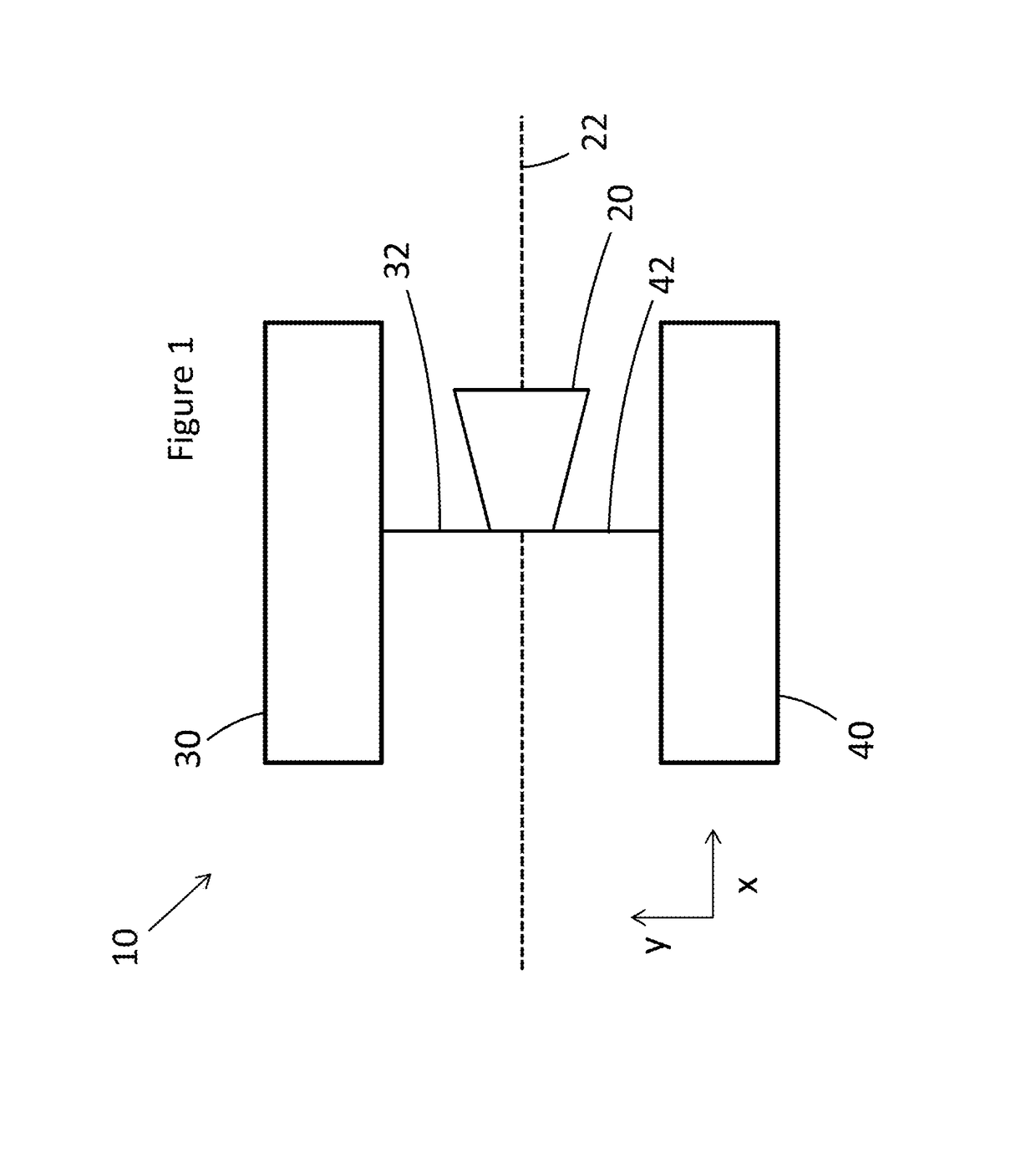
[0014]FIG. 1 shows part of a combined cycle power plant 10, including a steam turbine 20, a first heat recovery steam generator (first HRSG) 30 and a second heat recovery steam generator (second HRSG) 40. The first and second HRSGs are arranged on either side of the steam turbine 20. The first and second HRSGs are placed adjacent to the steam turbine and on opposite sides of the rotation axis 22 of the steam turbine. The steam turbine 20 is attached to the first HRSG by a first steam pipe system 32, and to the second HRSG by a second steam pipe system 42. The steam pipe systems 32, 42 transport steam between the HRSGs 30, 40 and the steam turbine 20.

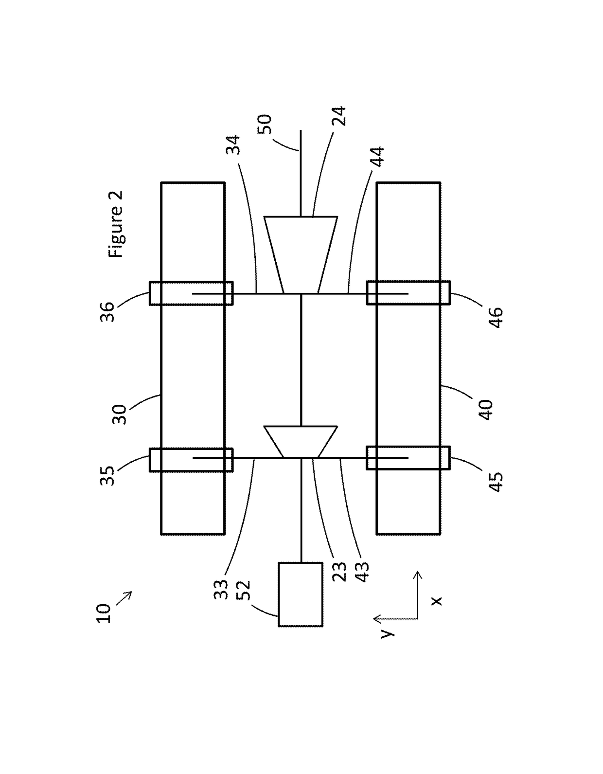
[0015]FIG. 2 shows another example of a combined cycle power plant 10. Instead of only one steam turbine as shown in FIG. 1, a high-pressure (HP) steam turbine 23 and an intermediate-pressure (IP) steam turbine 24 are provided. One, two or more low-pressure (LP) steam turbines (not shown) can also be provided downstream of the IP steam t...


PUM


Abstract

A combined cycle power plant is described, comprising a steam turbine, a first heat recovery steam generator and a second heat recovery steam generator. The first heat recovery steam generator is attached to the steam turbine by a first steam pipe system and the second heat recovery steam generator is attached to the steam turbine by a second steam pipe system, to allow steam to pass from the first and second heat recovery steam generators to the steam turbine. The steam turbine is arranged in between the first heat recovery steam generator and the second heat recovery steam generator.

Description

TECHNICAL FIELD[0001]The present disclosure relates to combined cycle power plants, and more particularly, to combined cycle power plants including a steam turbine, a first heat recovery steam generator, and a second heat recovery steam generator.BACKGROUND OF THE INVENTION[0002]In existing multi-shaft combined cycle power plants (CCPPs), steam turbines are typically arranged apart from the heat recovery steam generators (HRSGs) that supply them. It has been appreciated, however, that the arrangement of steam turbines with respect to heat recovery steam generators in CCPPs can be improved.BRIEF DESCRIPTION[0003]A first aspect provides a combined cycle power plant including a steam turbine, a first heat recovery steam generator and a second heat recovery steam generator. The first heat recovery steam generator is attached to the steam turbine by a first steam pipe system and the second heat recovery steam generator is attached to the steam turbine by a second steam pipe system to all...

Claims


Application Information

Patent Timeline
Patent Type & Authority Patents(United States)
IPC IPC(8): F01K23/10F01K23/16H02K7/18F02C6/00
CPCF01K23/10F01K23/106F02C6/00H02K7/1823F01K23/16Y02E20/16F01K23/02
Inventor TRIPPOLD, SIEGFRIEDKOENIG, ANDREROY CHOUDHURY, ATISH DIPANKARCANTIN, PATRICE RICHARDALIKHANI, REZAAGRAWAL, PRASHANT
Owner GENERAL ELECTRIC TECH GMBH
Learn More