Orthogonal-mode laser gyroscope

a laser gyroscope and orthogonal-mode technology, applied in the direction of the sagnac effect gyrometer, etc., can solve the problems of fiber optic gyroscopes, poor reliability, mechanical gyros that are typically quite large and massive, etc., to reduce or eliminate optical coupling, reduce or mitigate frequency lock-up

Active Publication Date: 2019-01-15
RGT UNIV OF CALIFORNIA
View PDF10 Cites 3 Cited by
  • Summary
  • Abstract
  • Description
  • Claims
  • Application Information

AI Technical Summary

Benefits of technology

[0009]The present invention enables a ring-laser gyroscope in which frequency lock-up is mitigated by imparting an orthogonality on counter-propagating light signals to reduce or eliminate optical coupling between them. By making the CW and CCW propagating light signals orthogonal, any coupling between the light signals has little or no effect on either signal. In some embodiments, the orthogonality is provided by imparting an optical frequency difference on them such that their frequencies are different enough to avoid interference between them. In some embodiments, the orthogonality is imparted by providing the light signals with orthogonal polarizations.

Problems solved by technology

Unfortunately mechanical gyros are typically quite large and massive.
They are also typically sensitive to shock and vibration, and can have poor reliability due to fabrication tolerances, as well as mechanical wear over time.
Unfortunately, prior-art fiber optic gyroscopes suffer from an effect often referred to as “frequency lock-up,” which makes them unable to sense rotation that is below a certain threshold.
This frequency lock-up is sometimes solved by introducing mechanical dither to the system, but mechanical nature of dither system can reduce the reliability and performance under large shock and vibration.
The need for a fiber-optic gyroscope that does not exhibit frequency lock-up at low rotation rates remains, as yet, unmet in the prior art.

Method used


Image

  • Orthogonal-mode laser gyroscope
  • Orthogonal-mode laser gyroscope
  • Orthogonal-mode laser gyroscope

Examples


Embodiment Construction

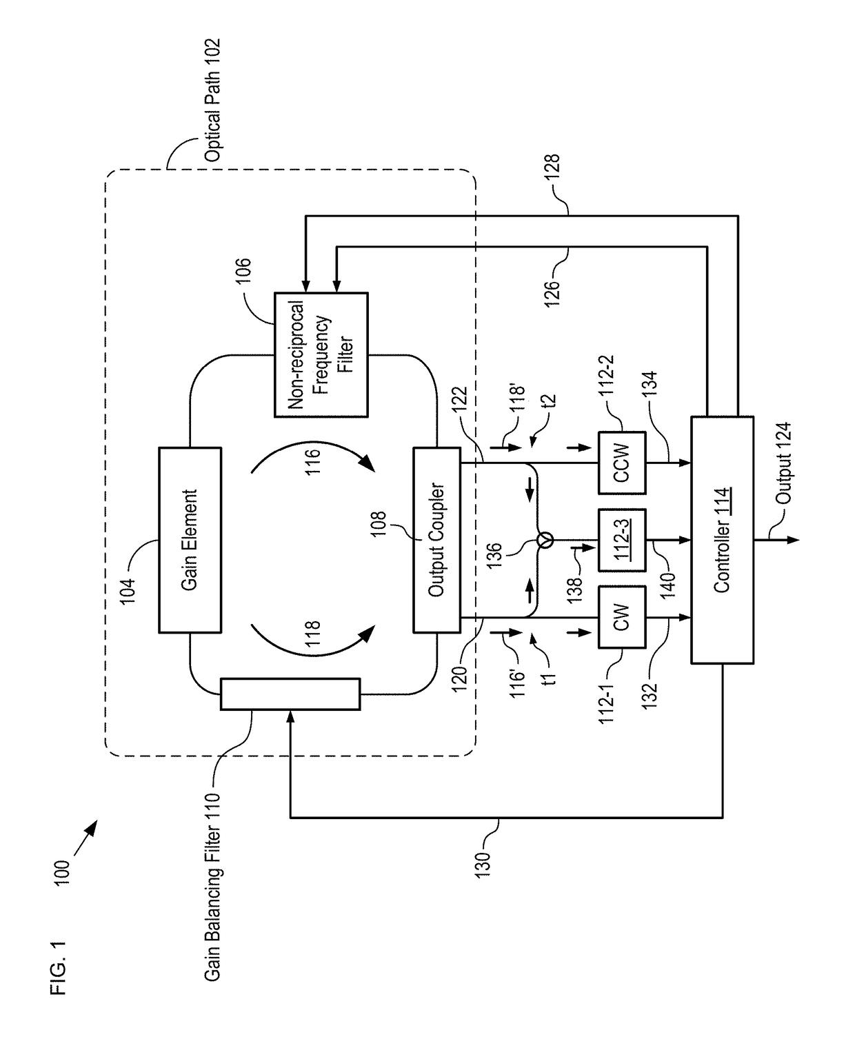
[0035]FIG. 1 depicts a schematic diagram of a ring-laser gyroscope in accordance with an illustrative embodiment of the present invention. RLG 100 comprises optical path 102, gain element 104, non-reciprocal frequency filter 106, output coupler 108, gain-balancing filter 110, detectors 112-1 through 112-3, controller 114, taps t1 and t2, and combiner 136.

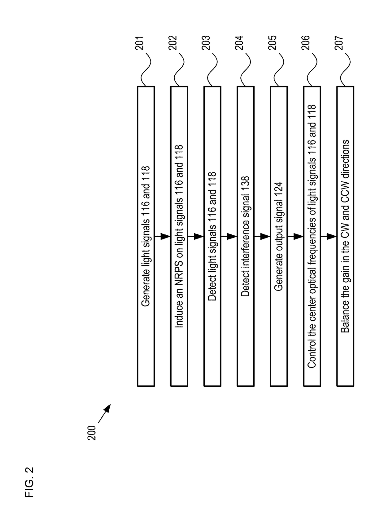
[0036]FIG. 2 depicts operations of a method for detecting rotation in accordance with the illustrative embodiment of the present invention. Method 200 begins with operation 201, wherein RLG 100 generates light signals 116 and 118 in optical path 102. Method 200 is described herein with continuing reference to FIG. 1 as well as reference to FIGS. 3-5.

[0037]Optical path 102 is a closed-loop planar-lightwave circuit (PLC) comprising an integrated-optics waveguide formed as a substantially rectangular loop. The waveguide is optically coupled with each of optical gain element 104, non-reciprocal frequency filter 106, output coupler 108, ...


PUM


Abstract

A fiber-optic gyroscope is disclosed, wherein the fiber-optic gyroscope has counter-propagating light signals in a closed-loop optical path, and where the light signals are characterized by an orthogonality that mitigates optical coupling between them. In some embodiments, the orthogonality is a difference in frequency of the two signals. In some embodiments, the orthogonality is a difference in the polarizations of the two signals. The orthogonality is imparted on the light signals by a non-reciprocal element that is optically coupled with the optical path. In some embodiments, a gain-balancing filter is also included to ensure that the loop gain for each light signal is substantially equal to one. In some embodiments, the light signals are provided by a gain element that is characterized by inhomogeneous broadening.

Description

RELATED APPLICATIONS[0001]This application claims the benefit of U.S. Provisional Application No. 62 / 326,152 filed Apr. 22, 2016. The entire disclosure of U.S. Provisional Application No. 62 / 326,152 is incorporated herein by reference.FIELD OF THE INVENTION[0002]The present invention relates to inertial navigation devices in general, and, more particularly, to ring laser gyroscopes.BACKGROUND OF THE INVENTION[0003]Gyroscopes (a.k.a., gyros) are devices used to sense rotation. They have become a nearly indispensable tool for use in inertial navigation of objects and vehicles (particularly when reliance on a magnetic compass is insufficient or not possible), as well as many other applications. Rotational sensing is critical for precise guidance, and is often used in conjunction with accelerometers to enable “dead reckoning” of the position, orientation, speed, etc., of a moving object, such as a ship, submarine, satellite, guided missile, and the like. Increasingly, gyroscopes are mak...

Claims


Application Information

Patent Timeline
Patent Type & Authority Patents(United States)
IPC IPC(8): G01C19/66
CPCG01C19/66
Inventor BOWERS, JOHN E.KOMLJENOVIC, TINHELKEY, ROGER
Owner RGT UNIV OF CALIFORNIA
Why Eureka
Try Eureka