
Charge control device

a charge control and control device technology, applied in emergency power supply arrangements, transportation and packaging, sustainable buildings, etc., can solve the problems of increasing the number of generation of solar power generation systems, reducing the output voltage of solar cells, etc., and achieve the effect of reducing the frequency of operating the charge control devi

Active Publication Date: 2019-01-15
DENSO TEN LTD +1
View PDF63 Cites 1 Cited by
  • Summary
  • Abstract
  • Description
  • Claims
  • Application Information

AI Technical Summary

Benefits of technology

The present invention is a charge control device for an electric storage device, such as a battery, that can be charged by a solar cell. The device uses an interval variable means to increase the predetermined interval in response to the number of consecutive prohibitions of the charge operation. This allows the device to capture charge opportunities and improve durability while reducing the amount of electric power consumed. The device also uses the open circuit voltage of the solar cell as an electric power generation index, which is correlated with the output electric power of the solar cell. The charge activation control means determines whether the charge start condition is satisfied based on the open circuit voltage of the solar cell. This reduces the frequency of executing the process and further improves the charging efficiency of the electric storage device.

Problems solved by technology

Thus, in case that a system activation timing is set on the basis of the open circuit voltage of the solar cell, even when the sunlight intensity is small and thus, a generated electric power is insufficient, the solar power generation system is actually activated.
In addition, under such a circumstance, after the activation of the solar power generation system, the output voltage of the solar cell decreases within a short time and as a result, the number of generations of an electric power carried out the solar power generation system may be caused to be increased.

Method used


Image

  • Charge control device
  • Charge control device
  • Charge control device

Examples


Embodiment Construction

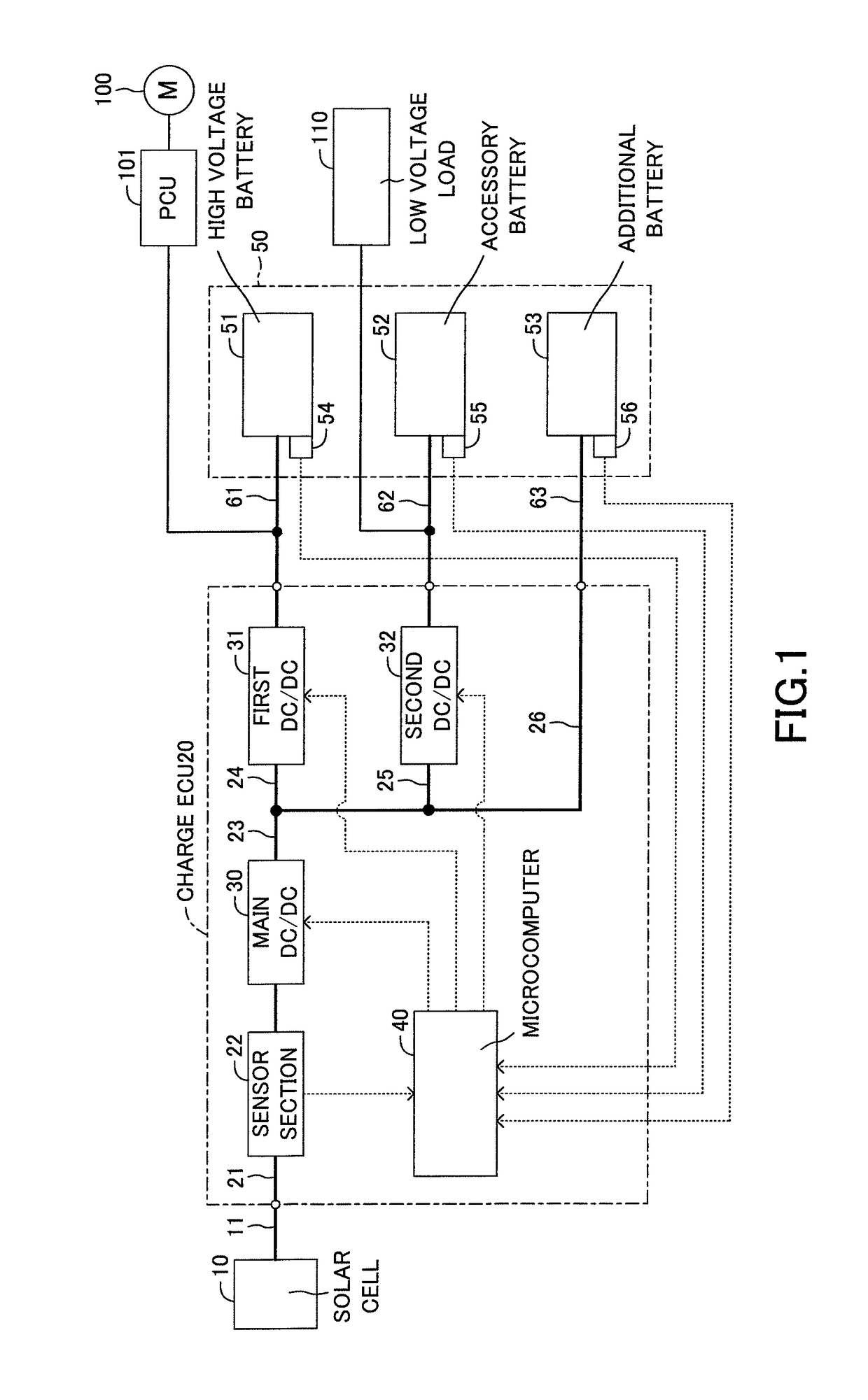
[0024]Below, a charge control device according to an embodiment of the present invention will be described with reference to the drawings. FIG. 1 shows a schematic configuration view of a solar power generation system provided with the charge control device according to this embodiment. The solar power generation system according to this embodiment is applied to a vehicle, however, an application range of this solar power generation system is not limited to the vehicle. The solar power generation system includes a solar cell 10, a charge control unit 20 and an electric storage device 50. For example, the solar cell 10 includes solar panels positioned on a roof of the vehicle and is an electric power appliance for converting an energy of sunlight received by the solar panels to an electric energy. The charge control unit 20 is a control device for charging the electric storage device 50 with an electric power generated by the solar cell 10 and corresponds to a charge control device a...


PUM


Abstract

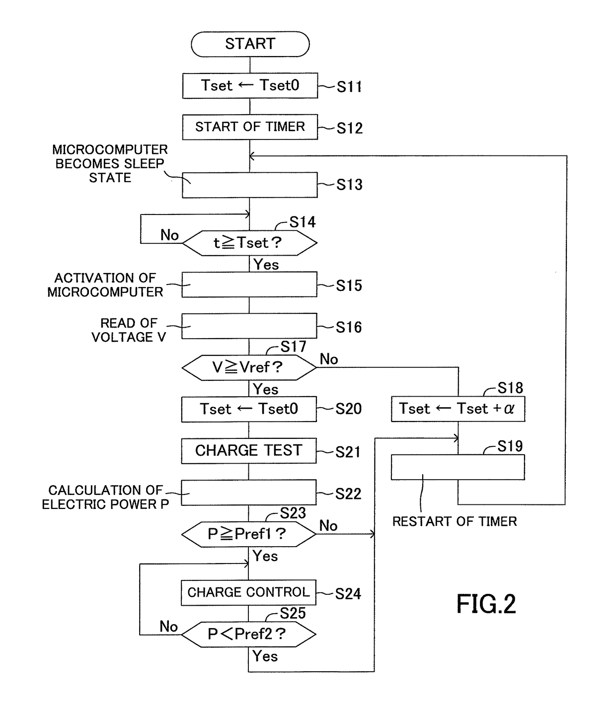
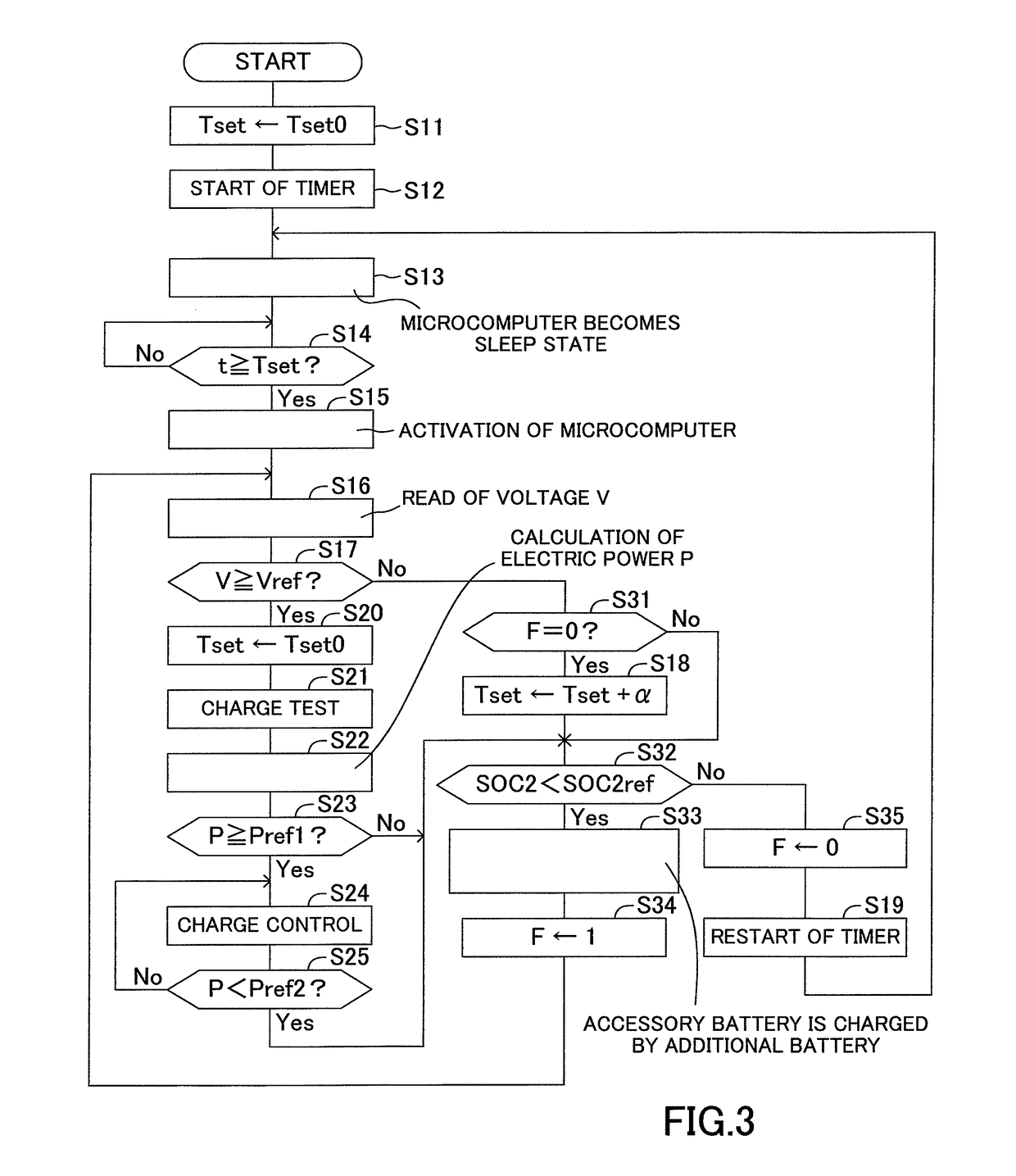
When a microcomputer does not charge an electric storage device, the microcomputer activates at an interval set based on a timer set value and determines whether an electric power voltage generated by a solar cell is equal to or higher than an electric power generation determination threshold. When the generated electric power voltage is lower than the electric power generation determination threshold, the microcomputer turns to a sleep state after increasing the timer set value by an addition set value while prohibiting charging the electric storage device. When the generated electric power voltage is equal to or higher than the electric power generation determination threshold and a generated electric power amount is equal to or larger than an electric power generation determination threshold, the microcomputer starts charging the electric storage device so the electric power device can be appropriately charged with an electric power generated by the solar cell.

Description

CROSS REFERENCE TO RELATED APPLICATIONS[0001]This is a National Stage of International Application No. PCT / JP2014 / 060419 filed Apr. 10, 2014, claiming priority based on Japanese Patent Application No. 2013-127087 filed Jun. 18, 2013, the contents of all of which are incorporated herein by reference in their entirety.TECHNICAL FIELD[0002]The present invention relates to a charge control device for charging an electric storage device with an electric power generated by a solar cell.BACKGROUND ART[0003]Conventionally, for example, as proposed in JP 2012-196022 A, there is known a solar power generation system which includes a solar cell provided with solar panels, an electric storage device and a charge control device for charging the electric storage device with an electric power generated by the solar cell. In such a solar power generation system, when the solar cell generates an electric power, in other words, when the sun shines, the charge control device is configured to be activa...

Claims


Application Information

Patent Timeline
Patent Type & Authority Patents(United States)
IPC IPC(8): H02J7/00H02J7/35H02J9/06H02J5/00H02M1/00
CPCH02J7/35H02J7/007H02J5/00Y10T307/615H02M2001/009Y02B10/72H02J9/062Y02B10/70H02M1/009
Inventor MAENO, SEIGENHIBINO, TAKUYAOCHI, YOHSUKE
Owner DENSO TEN LTD
Learn More