Switch module

a technology of switch module and shunt connection, which is applied in the field of switch module, can solve the problems of increasing the insertion loss of this series-connected switch, difficult to find suitable values, and difficult to reduce the insertion loss of a switch module including shunt-connected switches, so as to reduce the insertion loss of the switch module

Active Publication Date: 2019-01-15
MURATA MFG CO LTD
View PDF18 Cites 7 Cited by
  • Summary
  • Abstract
  • Description
  • Claims
  • Application Information

AI Technical Summary

Benefits of technology

[0005]In the above-described configuration, in order to more reliably prevent a signal leakage by turning OFF the switch, a shunt-connected switch is usually provided between a signal path and a ground point. For example, Japanese Unexamined Patent Application Publication No. 2014-93610 discloses a radio-frequency switch circuit including shunt-connected switches that connect a signal path and a ground point. In this radio-frequency switch circuit, the shunt-connected switches are turned ON so that the input impedance will be made to be almost 0 to cause impedance mismatching, thereby eliminating the influence of the impedance of a circuit connected to the radio-frequency switch circuit. In the radio-frequency switch circuit disclosed in this publication, a SPnT switch module including shunt-connected switches provided in a signal path from a common terminal P1 to input / output terminals P2 through P7 is provided.
[0007]As in the switch module disclosed in this publication, a shunt-connected switch may be disposed on a signal path from a common terminal P1 to each input / output terminal. In this case, in order to reduce the insertion loss, which may occur when a certain series-connected switch is turned ON, the capacitance of another series-connected switch that is turned OFF may be decreased so that power of leakage which may occur via this capacitance can be reduced. However, decreasing of the capacitance of a series-connected switch that is turned OFF increases the resistance of this series-connected switch when it is turned ON, thereby increasing the insertion loss of this series-connected switch. In this manner, the capacitance of a series-connected switch that is turned OFF and the resistance of this series-connected switch that is turned ON have a tradeoff relationship. It is difficult to find suitable values of the capacitance and the resistance of a series-connected switch which may contribute to reducing the insertion loss of the overall switch module. It is thus difficult to reduce the insertion loss of a switch module including shunt-connected switches.
[0008]The present disclosure has been made in view of the above-described background. The present disclosure reduces the insertion loss of a switch module.
[0011]In a switch module according to an embodiment of the present disclosure, the impedance of the first filter seen from an end portion of the first switch connected to the first filter is not to be made in the short state, thereby making it possible to reduce the insertion loss of the switch module.

Problems solved by technology

However, decreasing of the capacitance of a series-connected switch that is turned OFF increases the resistance of this series-connected switch when it is turned ON, thereby increasing the insertion loss of this series-connected switch.
It is difficult to find suitable values of the capacitance and the resistance of a series-connected switch which may contribute to reducing the insertion loss of the overall switch module.
It is thus difficult to reduce the insertion loss of a switch module including shunt-connected switches.

Method used


Image

  • Switch module
  • Switch module
  • Switch module

Examples


first embodiment

[First Embodiment]

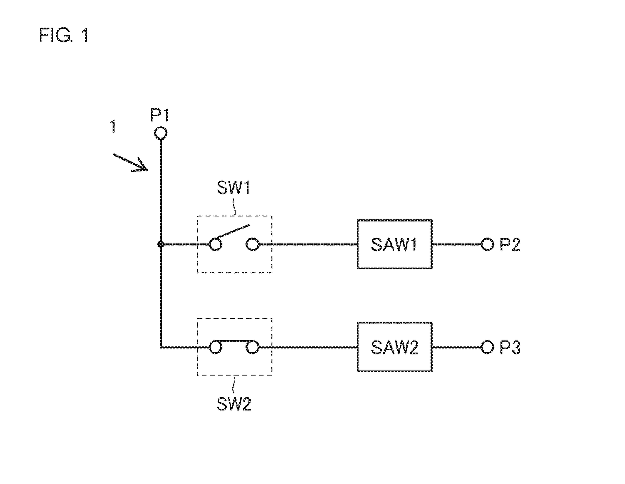
[0032]FIG. 1 is a circuit diagram of a switch module 1 according to a first embodiment. As shown in FIG. 1, the switch module 1 includes a common terminal P1, input / output terminals P2 and P3, first and second filters SAW1 and SAW2, which are surface acoustic wave (SAW) filters, and first and second switches SW1 and SW2. The pass band of the second filter SAW2 is included in the stop band of the first filter SAW1. The switch module 1 is a single-pole double-throw (SPDT) switch module. Alternatively, the switch module 1 may be a SPnT (n is three or greater) switch module.

[0033]The common terminal P1 corresponds to a first terminal of an embodiment of the disclosure. The pass band of the first filter SAW1 corresponds to a first frequency band of an embodiment of the disclosure, and the stop band of the first filter SAW1 corresponds to a second frequency band of an embodiment of the disclosure. The pass band of the second filter SAW2 corresponds to a third frequency b...

second embodiment

[Second Embodiment]

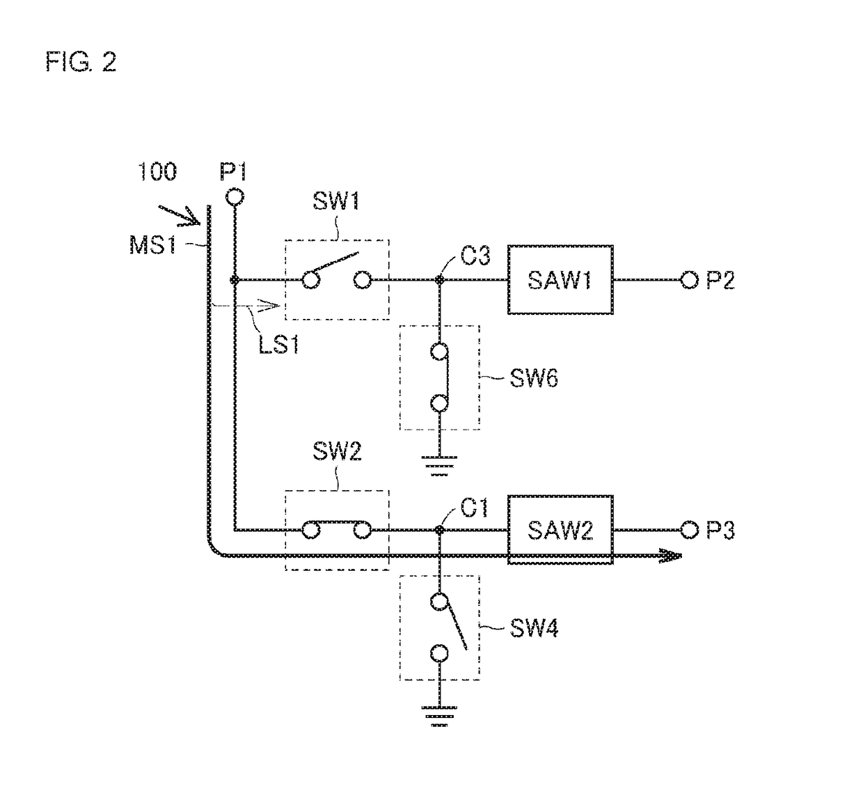
[0083]In the first embodiment, without the provision of a shunt-connected switch, a connection path from a series-connected switch to a SAW filter is not connected to a ground point so that the impedance from the common terminal P1 to each input / output terminal can be made to be in the open state. However, other measures may be taken to make the impedance from the common terminal P1 to each input / output terminal be in the open state. Any measures may be taken not to connect a connection path from a series-connected switch to a SAW filter to a ground point. In a second embodiment, shunt-connected switches are provided, and regardless of whether series-connected switches are ON or OFF, the shunt-connected switches are turned OFF, so that a connection path from a series-connected switch to a SAW filter is not connected to a ground point. In the second embodiment, the configurations of elements designated by like reference numerals of the first embodiment are similar ...

first modified example

[First Modified Example of Second Embodiment]

[0088]In a first modified example of the second embodiment, a switch module 2A (FIG. 11) includes a shunt-connected switch because the pass bands of two filters in the switch module 2A overlap each other, as in the first modified example of the first embodiment. The first modified example of the second embodiment differs from the first modified example of the first embodiment in that the sixth switch SW6 discussed in the second embodiment is connected between a ground point and the third node C3 between the first switch SW1 and the first filter SAW1. The configurations of the other elements are similar to those of the first modified example of the first embodiment, and an explanation thereof will thus be omitted.

[0089]In the first modified example of the second embodiment, it is possible to reduce the insertion loss of the switch module 2A, as in the first modified example of the first embodiment.


PUM


Abstract

A switch module includes a first terminal, first and second filters, and first and second switches. Impedance of the first filter for a signal in a stop band is capacitive. When the first switch is turned OFF, impedance of the first switch is capacitive, and impedance of the first filter seen from an end portion of the first switch connected to the first filter is not in a short state and impedance of the first filter seen from the first terminal is in an open state.

Description

[0001]This application claims priority from Japanese Patent Application No. 2016-096032 filed on May 12, 2016. The content of this application is incorporated herein by reference in its entirety.BACKGROUND[0002]The present invention relates to a switch module that switches between signal paths in accordance with the frequency band.[0003]Electronic devices that transmit and receive signals by using multiple frequency bands are known. In such electronic devices, a switch module that switches between signal paths in accordance with the frequency band may be used. In this switch module, a signal of a certain frequency band may leak from a terminal other than a target output terminal. This may cause a device or a circuit connected to such a terminal to malfunction. In order to improve the performance of such a switch module, it is necessary to enhance isolation characteristics representing the degree of isolation between terminals.[0004]Japanese Unexamined Patent Application Publication ...

Claims


Application Information

Patent Timeline
Patent Type & Authority Patents(United States)
IPC IPC(8): H01P1/10H03H9/00H03H9/64H03H9/72H03H7/40
CPCH03H9/725H03H9/64H03H9/0009H03H7/40H03K17/687H04B1/40H04B1/0057H04B1/006H04B1/525
Inventor TOMITA, TAKAYUKIWATANABE, DAISUKE
Owner MURATA MFG CO LTD
Why Eureka
Try Eureka