Nutrient removal filtration system and method

a filtration system and nutrient technology, applied in the field of storm water treatment, can solve the problems of significant friction between water and media, limited system size, and ineffective removal of dissolved pollutants, and achieve the effect of easy vacuuming and high clean levels

Inactive Publication Date: 2019-01-22
OLDCASTLE INFRASTRUCTURE INC
View PDF22 Cites 14 Cited by
  • Summary
  • Abstract
  • Description
  • Claims
  • Application Information

AI Technical Summary

Benefits of technology

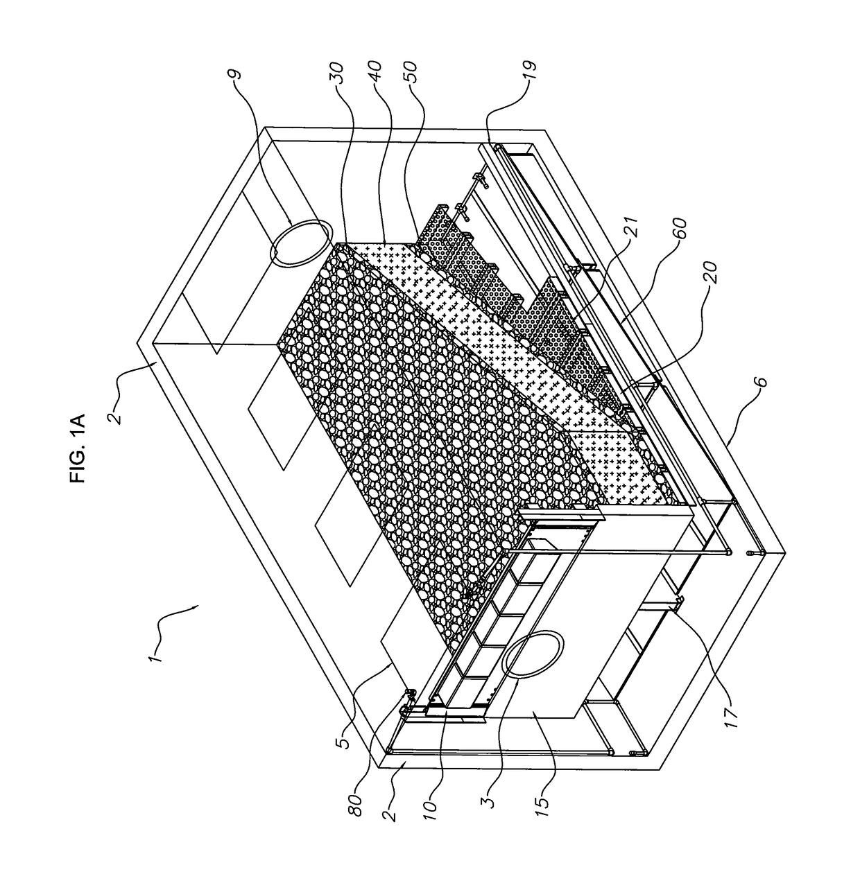
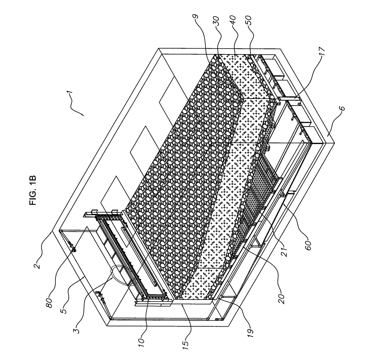
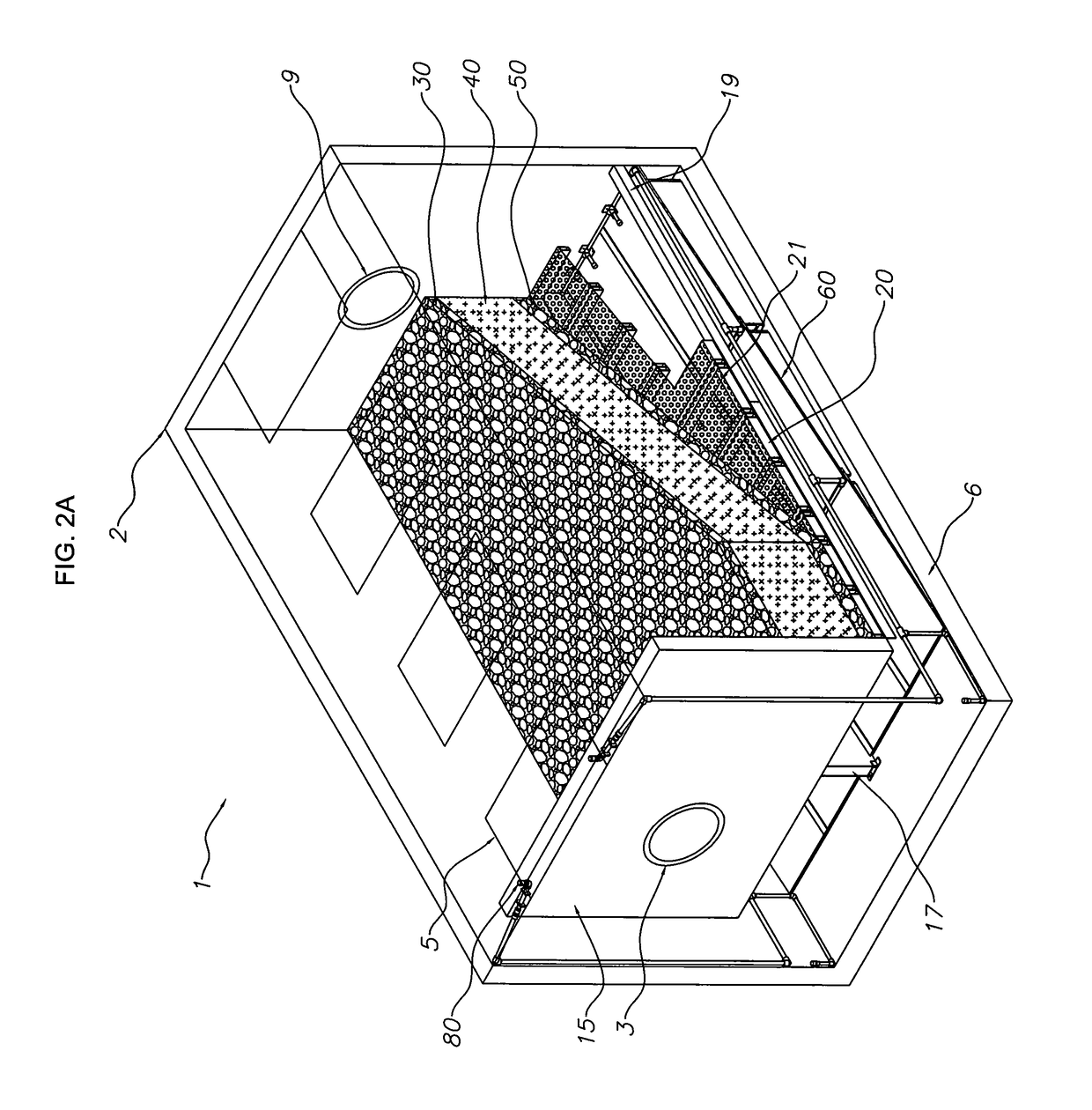
[0010]A primary objective of the present invention is to provide systems, devices, and methods for providing nutrient removals in an up flow filtration storm water system for treating water to high clean levels using filtration media and a screen, where captured debris slide down a sloped floor to a low point where the debris can be liquefied by water sprayers followed by being easily vacuum removed.

Problems solved by technology

However, these types of systems are limited to the size of the pollutants being removed, and are not very efficient for removing dissolved pollutants such as dissolved phosphorus and nitrogen, etc.
However, a problem with using filter media in a storm water treatment system is the significant influence of friction between the water and the media.
In addition, changing the direction of water flow as it passes through a filtration system reduces the kinetic energy of the water flow which will reduce the volume water flow.
During big rain events a storm water filtration system in a storm water pipe can significantly inhibit the passage of water and cause flooding upstream from the filtration system.
The problem is that the size of the cartridges are limited to a size that can be removed from the vault during servicing.
Additionally, there are void spaces between the cartridges, and these spaces are not able to be engaged in the treatment process.
However, these patents and all the prior art have additional problems of what happens to the debris which will land spread out across the entire floor of the vault.
Having to service debris that is located everywhere on the floor makes it difficult and time consuming to later remove that debris.

Method used


Image

  • Nutrient removal filtration system and method
  • Nutrient removal filtration system and method
  • Nutrient removal filtration system and method

Examples


Embodiment Construction

[0058]Before explaining the disclosed embodiments of the present invention in detail it is to be understood that the invention is not limited in its applications to the details of the particular arrangements shown since the invention is capable of other embodiments. Also, the terminology used herein is for the purpose of description and not of limitation.

[0059]In the Summary above and in the Detailed Description of Preferred Embodiments and in the accompanying drawings, reference is made to particular features (including method steps) of the invention. It is to be understood that the disclosure of the invention in this specification does not include all possible combinations of such particular features. For example, where a particular feature is disclosed in the context of a particular aspect or embodiment of the invention, that feature can also be used, to the extent possible, in combination with and / or in the context of other particular aspects and embodiments of the invention, an...


PUM

PropertyMeasurementUnit
sizeaaaaaaaaaa
sizeaaaaaaaaaa
pressureaaaaaaaaaa

Abstract

Systems, devices, and methods for providing nutrient removals in an up flow filtration storm water system for treating water to very high clean levels using filtration media. A filtration media supported by a screen above an angled floor in a vault allows for incoming storm water to pass into a void space above the angled floor into the screen and filtration media and then out an outlet to the vault. The filtration media can include recyclable and/or natural particles. Layers of river rocks can be placed on top of and below the filtration media. Water sprayers can further liquefy sediment and debris that fills the void space between the angled floor and the bottom of the screen. The captured debris can slide down the angled floor, where a vacuum hose from an above ground vacuum truck can remove the debris and sediment. The long lasting filtration media can be cleaned by being backwashed.

Description

CROSS REFERENCE TO RELATED APPLICATIONS[0001]This application is a Continuation-In-Part of U.S. Patent application Ser. No. 14 / 288,455 filed May 28, 2014, now abandoned, which claims the benefit of priority to U.S. Provisional Patent Application Ser. No. 61 / 828,958 filed May 30, 2013. The entire disclosure of each of the applications listed in this paragraph are incorporated herein by specific reference thereto.FIELD OF INVENTION[0002]This invention relates to storm water treatment, and in particular to systems, devices, and methods for providing nutrient removals in an up flow filtration storm water system for treating water to high clean levels using filtration media and a screen, where captured debris slide down a sloped floor to a low point where the debris can be liquefied by water sprayers followed by being easily vacuum removed.BACKGROUND AND PRIOR ART[0003]Federal clean water requirements require water bodies such as lakes and rivers that must meet strict minimal water quali...

Claims


Application Information

Patent Timeline
Patent Type & Authority Patents(United States)
IPC IPC(8): E03F5/14B01D24/46E03F5/04B01D24/36B01D24/00B01D21/00E03F5/10B01D21/24B01D24/16
CPCB01D21/0012B01D24/007B01D24/36B01D21/0042B01D21/2472B01D24/4631E03F5/108E03F5/0404E03F5/0403B01D24/165E03F5/14B01D2101/04
Inventor HAPPEL, THOMAS
Owner OLDCASTLE INFRASTRUCTURE INC
Why Eureka
Try Eureka