
Surround sensing system with telecentric optics

a sensing system and optics technology, applied in the field of surround sensing systems with telecentric optics, can solve the problems of limited depth sensitivity, poor angular and depth resolution in certain applications, and limited depth sensitivity, so as to reduce the loss of underlying sensor fill factor, reduce the overall intensity of light arriving, and avoid pixel saturation

Active Publication Date: 2019-01-22
XENOMATIX NV
View PDF14 Cites 45 Cited by
  • Summary
  • Abstract
  • Description
  • Claims
  • Application Information

AI Technical Summary

Benefits of technology

The system provides robust, high-resolution 3D profiling over extended ranges (up to 200 meters) with improved precision and reliability in various weather and light conditions, suitable for autonomous vehicles, while maintaining low power consumption and mechanical simplicity.

Problems solved by technology

Radar based systems have the advantage that they can sense a long range but have the disadvantage that they have a poor angular and depth resolution with regard to certain applications (e.g. for tracking the profile in a road).
Ultrasound based systems can be useful for short range sensing but their narrow bandwidth limits the depth sensitivity and the sampling resolution and the strong absorption in air limits the range to a few meters.
This system, which is primarily intended for indoor gaming and entertainment applications, is not suitable for outdoor use, due to the intensity of the sunlight.
On the other hand stereovision based systems have the disadvantage that calibrated cameras with sufficient distance are required.
Furthermore, sufficient structure in the images is required to enable cross correlation for parallax, it is difficult to detect flat surfaces and water, a sufficient number of pixels is required, the depth sensitivity is limited, and typical cameras have insufficient dynamic range to cope with various light conditions.
The biggest hurdle seems to be that stereovision based systems cannot work if there is insufficient structure in the object being scanned.
The systems mentioned above are not capable of operating sufficiently accurately at a high vehicle speed for a long detection range.

Method used


Image

  • Surround sensing system with telecentric optics
  • Surround sensing system with telecentric optics
  • Surround sensing system with telecentric optics

Examples


Embodiment Construction

[0084]The present invention will be described with respect to particular embodiments and with reference to certain drawings but the invention is not limited thereto but only by the claims. The drawings described are only schematic and are non-limiting. In the drawings, the size of some of the elements may be exaggerated and not drawn on scale for illustrative purposes. The dimensions and the relative dimensions do not correspond to actual reductions to practice of the invention.

[0085]Furthermore, the terms first, second and the like in the description and in the claims, are used for distinguishing between similar elements and not necessarily for describing a sequence, either temporally, spatially, in ranking or in any other manner. It is to be understood that the terms so used are interchangeable under appropriate circumstances and that the embodiments of the invention described herein are capable of operation in other sequences than described or illustrated herein.

[0086]Moreover, t...


PUM


Abstract

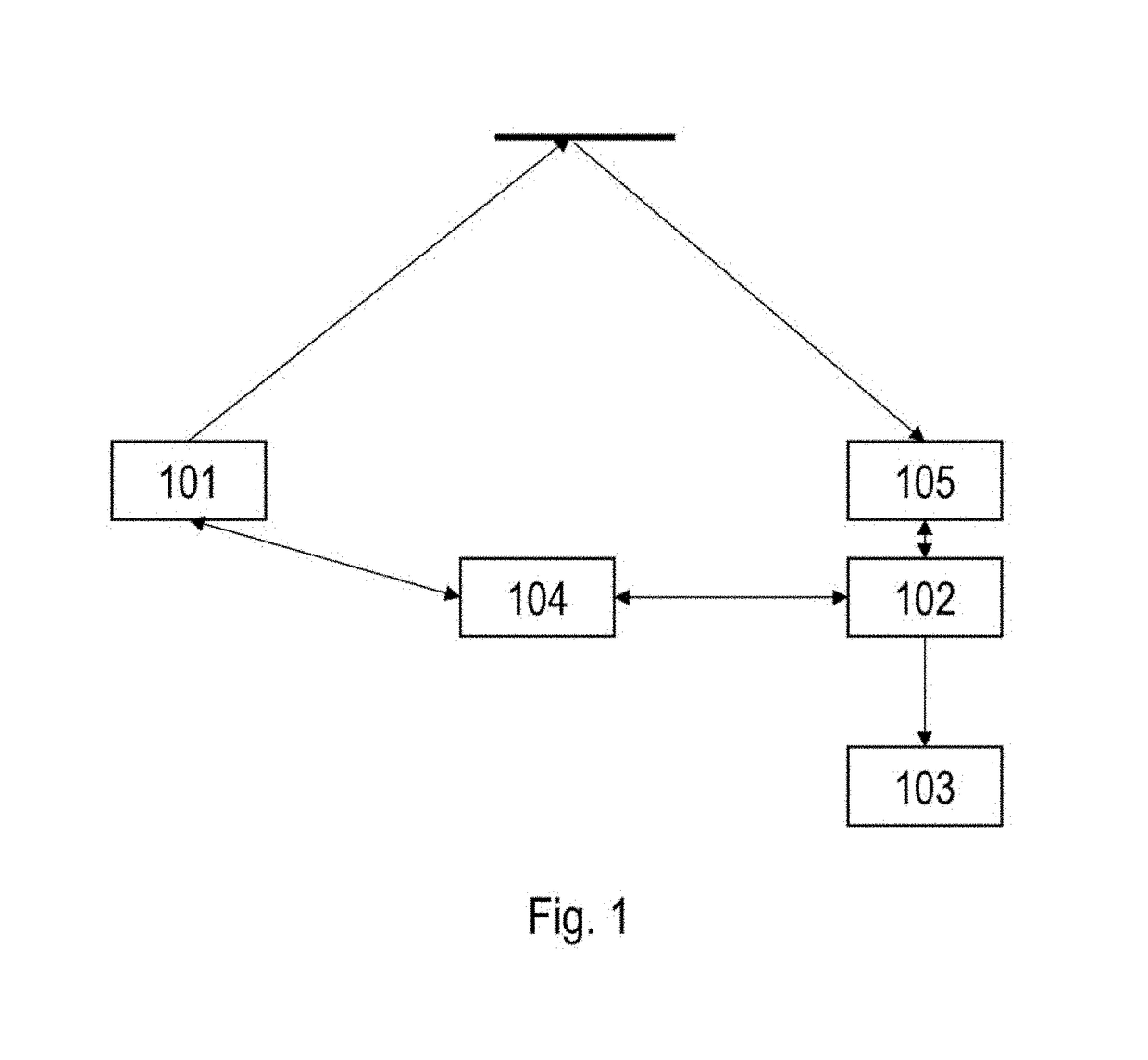
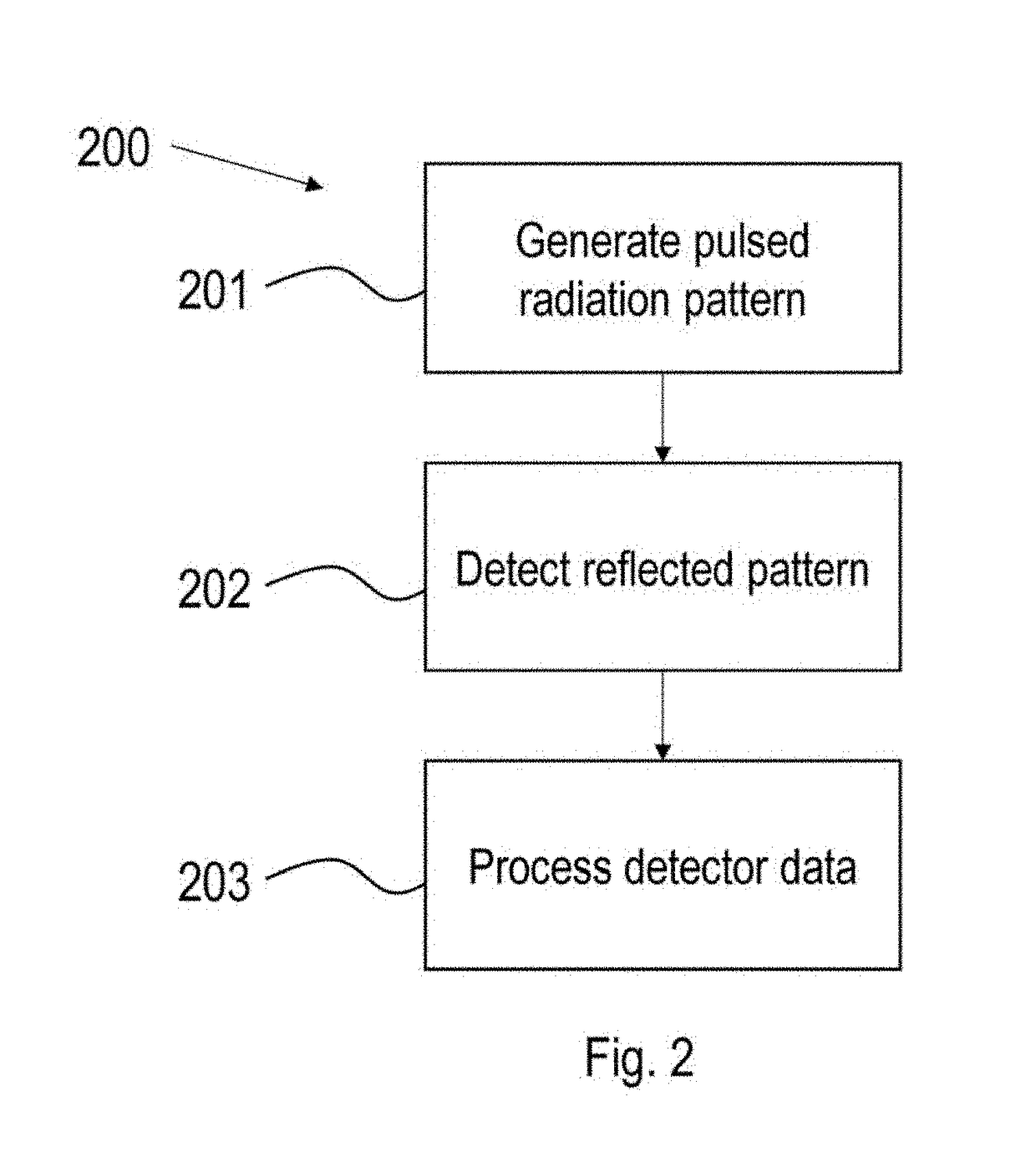
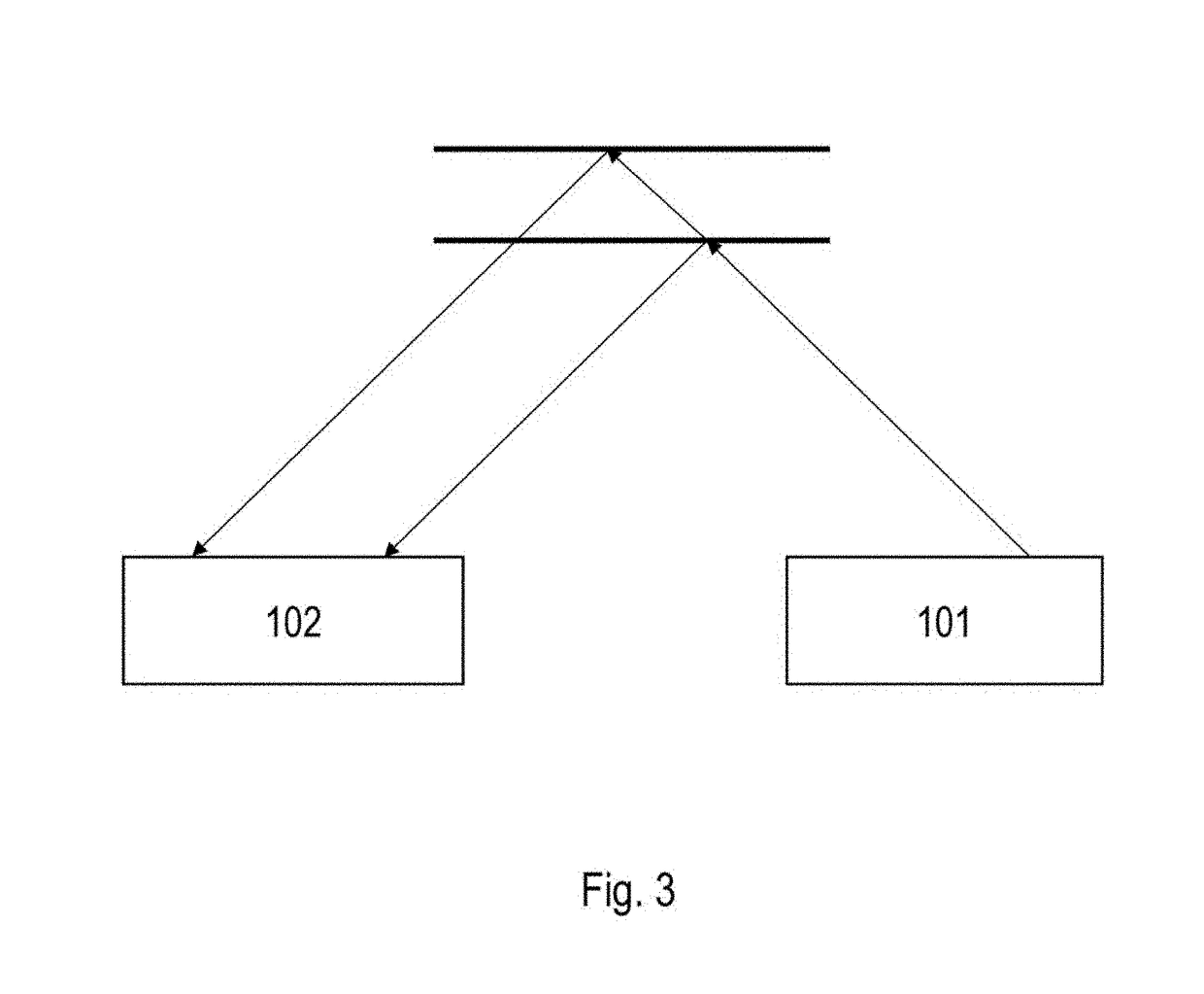
The invention pertains to a system comprising: a source to generate a pulsed radiation pattern; a detector; a processor to process data from the detector when radiation is reflected by an object; a synchronization means interfacing between the detector and the source; wherein: the detector is synchronized with the source so that radiation to be processed is detected only during the pulses, the processor determines a characteristic of the object by determining displacement of detected spots with reference to predetermined positions, the source emits monochromatic light and the detector is equipped with a bandpass filter and optics arranged so as to modify an angle of incidence onto said filter to confine light to a predetermined range around a normal of said filter, said optics comprising an image-space telecentric lens.

Description

[0001]The invention relates to the field of characterizing a scene or part thereof. More specifically it relates to systems and methods for detecting the characteristic, e.g. a profile or property, of an object or person, in particular in the vicinity of a vehicle.BACKGROUND OF THE INVENTION[0002]There are a large number of applications where knowledge of the 3D profile of an object is relevant. Different techniques exist for scanning the profile of an object. Basically they can be subdivided into radar based systems, ultrasound based systems and optical sensing systems.[0003]Radar based systems have the advantage that they can sense a long range but have the disadvantage that they have a poor angular and depth resolution with regard to certain applications (e.g. for tracking the profile in a road).[0004]Ultrasound based systems can be useful for short range sensing but their narrow bandwidth limits the depth sensitivity and the sampling resolution and the strong absorption in air l...

Claims


Application Information

Patent Timeline
Patent Type & Authority Patents(United States)
IPC IPC(8): B60G17/0165G01S7/486G05D1/02H04N13/207G01S17/46G01S17/89G01S7/481G01B11/24G01S17/93G01S7/487G01S7/4865G01S17/931
CPCB60G17/0165G01S7/4815G01S7/4816G01S7/4817G01S7/4865G01S17/46G01S17/89G01S17/93G01S17/936G05D1/0242H04N13/207G01B11/24G01S7/487B60G2400/82B60G2401/14G01S17/931
Inventor VAN DEN BOSSCHE, JOHANVAN DYCK, DIRKCONINGS, LIESBET
Owner XENOMATIX NV
Learn More