
Optical fiber arrangement for a system for measuring the light absorption or determining the concentration of a substance

a technology of optical fiber and light absorption, applied in the direction of optical radiation measurement, instruments, spectrophotometry/monochromators, etc., can solve the problems of transmission loss, requiring a relatively long optical fiber to allow a sufficient coupling of optical modes, and affecting the quality of optical fibers, etc., to achieve improved mode coupling and high quality

Active Publication Date: 2019-01-22
CYTIVA SWEDEN AB
View PDF19 Cites 0 Cited by
  • Summary
  • Abstract
  • Description
  • Claims
  • Application Information

AI Technical Summary

Benefits of technology

[0012]The object of the invention is to achieve an improved mode coupling in an optical fiber arrangement suitable for use in systems for measuring the light absorbance or determining the concentration of a substance. This is achieved through an optical fiber arrangement for inducing coupling among propagation modes of light according to the appended independent claim 1. Thereby, the mode coupling is performed in an efficient manner, achieving uniform output light of high quality.
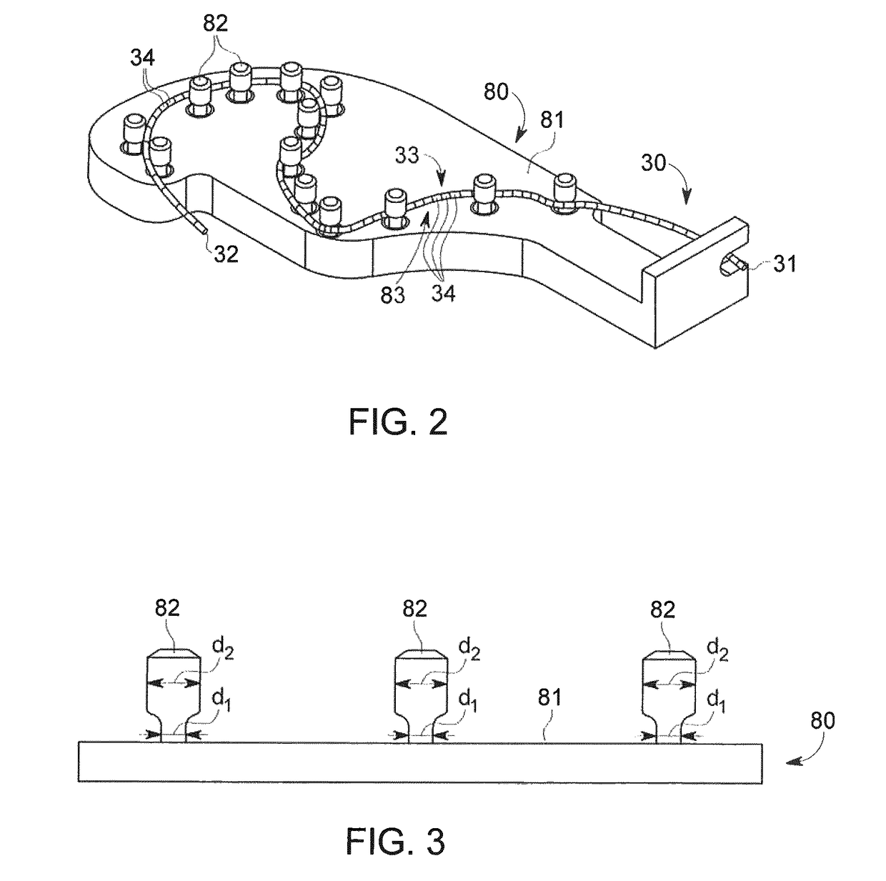
[0013]According to an aspect of the invention, the coupling inducing section of the optical fiber is arranged essentially in a plane on said holder. Thereby, the entire optical fiber arrangement can be made smaller and more stable, avoiding any movements of the coupling inducing section due to insufficient fixation, and the losses associated therewith.
[0014]According to a further aspect of the invention, the coupling inducing section of the optical fiber comprises a plurality of regions and each region is fixated in relation to said holder. Thereby, losses and drift that occur through position changes of the optical fiber, through temperature drift or due to external forces applied to the optical fiber can be minimized.
[0015]According to another aspect of the invention, the coupling inducing section is arranged along a path in said holder, said path comprising open bends such that no region of the coupling inducing section is arranged to overlap any other region. Thereby, any losses occurring through the movement or abutting of one part of the optical fiber on another can be minimized, and the fixation of the entire coupling inducing section is facilitated.
[0017]According to yet another aspect of the invention, at least one of the holding pins is movably arranged on the surface of the holder. Thereby, the fixation of the optical fiber can be further improved and tolerances in the length of the fiber can be compensated to achieve a secure fastening and prevent movements of the optical fiber.

Problems solved by technology

The mode coupling or mode mixing arrangement commonly used has the disadvantages of being bulky and requiring a relatively long optical fiber to allow for a sufficient coupling of optical modes.
Through the loops and bends, transmission losses also occur, especially in the deep UV region below 250 nm.

Method used


Image

  • Optical fiber arrangement for a system for measuring the light absorption or determining the concentration of a substance
  • Optical fiber arrangement for a system for measuring the light absorption or determining the concentration of a substance
  • Optical fiber arrangement for a system for measuring the light absorption or determining the concentration of a substance

Examples


Embodiment Construction

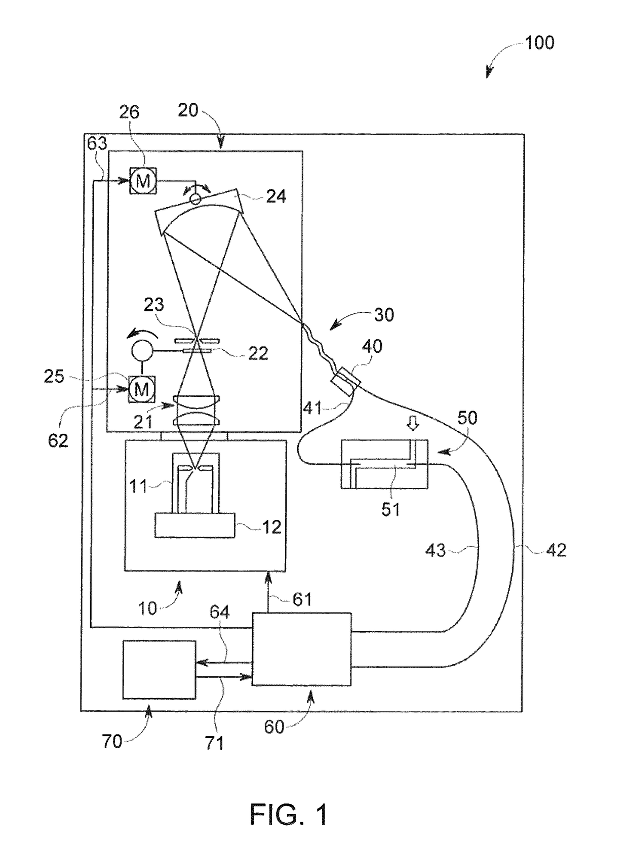
[0026]The optical fiber arrangement according to a preferred embodiment of the invention is suitable for use in a system for measuring the absorption or determining the concentration or a substance selected from the group comprising proteins, peptides, nucleic acids or cells within a solution. One example of such systems is a liquid chromatography system, and a typical system of this kind is disclosed by FIG. 1 and used below to illustrate the invention.

[0027]Thus, FIG. 1 shows a schematic diagram of a typical liquid chromatography system 100, including a spectrophotometer with a light source unit 10 comprising a light source 11 and a lamp trigger 12 that is arranged to control the light source 11 to emit flashes of light at predetermined intervals. The light source 11 can be a xenon lamp with a frequency of 100 Hz, but alternatively other suitable light sources can be used. Light emitted by the light source 11 propagates to a monochromator 20 and passes a condenser 21 to focus the ...


PUM

PropertyMeasurementUnit
frequencyaaaaaaaaaa
wavelengthsaaaaaaaaaa
concentrationaaaaaaaaaa

Abstract

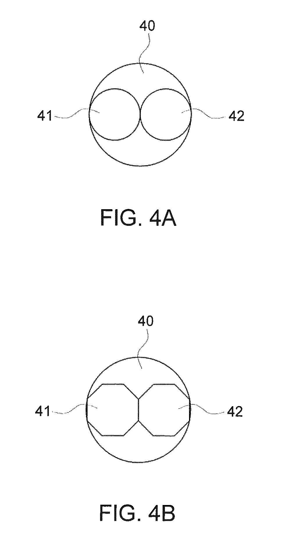
Disclosed is an optical fiber arrangement for inducing coupling among propagation modes of light, said arrangement comprising a multimode optical fiber (30) having an input end (32) for receiving light and an output end (31) for emitting light, with a coupling inducing section (33) extending from said input end to said output end, and a holder (80) on which the optical fiber is arranged, wherein said multimode optical fiber has a non-circular cross section. Disclosed also is a system for measuring the absorption or determining the concentration of a substance, said system comprising at least one optical fiber arrangement.

Description

CROSS REFERENCE TO RELATED APPLICATIONS[0001]This application claims the priority benefit of PCT / EP2015 / 080417 filed on Dec. 18, 2015 which claims priority benefit of U.S. Provisional Patent Application No. 62 / 093,481 filed Dec. 18, 2014. The entire contents of which are hereby incorporated by reference herein.FIELD OF THE INVENTION[0002]The present invention relates to an optical fiber arrangement for inducing coupling among propagation modes of light. The invention also relates to a system for measuring the light absorption or determining the concentration of a substance for example a substance suspended in a solution, said system comprising an optical fiber arrangement, for example in a liquid chromatography spectrophotometer.BACKGROUND OF THE INVENTION[0003]Optical detection methods are frequently employed in analytical instruments for sensitive detection of chemical compounds, such as biomolecules. Optical detection is particularly well suited for analytical techniques where th...

Claims


Application Information

Patent Timeline
Patent Type & Authority Patents(United States)
IPC IPC(8): G02B6/14G02B6/36G01J3/02G01J3/42G01N30/74G02B6/00G01N30/02G02B6/028
CPCG02B6/14G01J3/0218G01J3/42G02B6/3628G01N30/74G02B6/0288G01N2030/027G02B6/00G02B6/0006G02B6/0008
Inventor EHRING, HANNOYAZDANFAR, SIAVASHHORNQVIST, MIKAEL ANDERSZHONG, ZHANGYIMAO, YING
Owner CYTIVA SWEDEN AB
Learn More