Method for sensing fraudulent frames transmitted to in-vehicle network
a technology of fraudulent frames and in-vehicle transmission, which is applied in the direction of digital transmission, electric/fluid circuit, bus networks, etc., can solve the problems of fraudulent control of the vehicle body, and achieve the effect of reducing the consumption of the in-vehicle battery
- Summary
- Abstract
- Description
- Claims
- Application Information
AI Technical Summary
Benefits of technology
Problems solved by technology
Method used
Image
Examples
first embodiment
[0073]An embodiment of the present disclosure will now be described with reference to the drawings in the context of an in-vehicle network system 10 including a fraud-sensing ECU that implements an anti-fraud method for preventing a process based on a fraudulent frame from being executed on any other node (ECU) by using message IDs.
1.1 Overall Configuration of In-Vehicle Network System 10
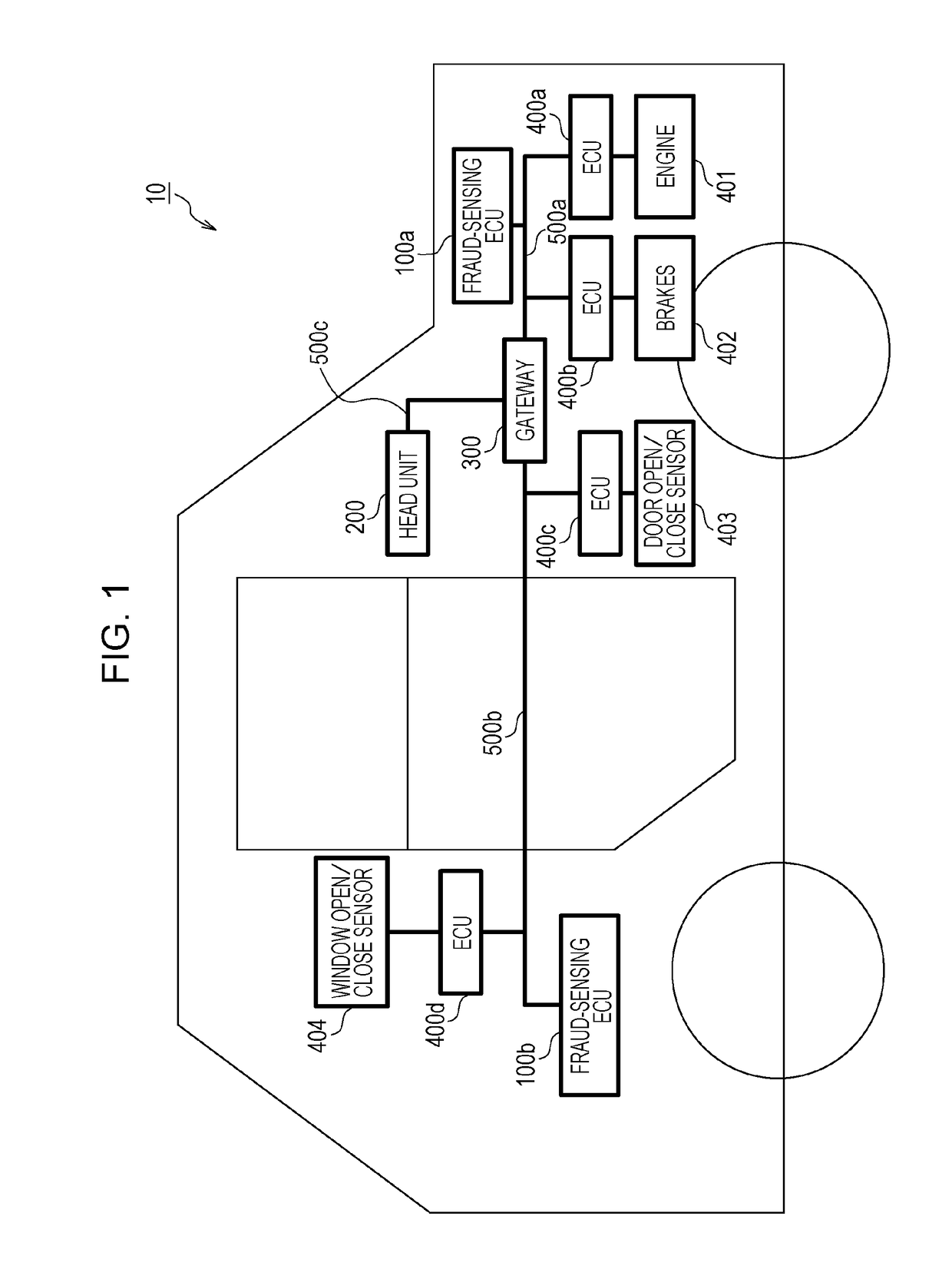
[0074]FIG. 1 is a diagram illustrating an overall configuration of an in-vehicle network system 10 according to a first embodiment. The in-vehicle network system 10 is an example of a network communication system in which communication is established in accordance with the CAN protocol, and is a network communication system in an automobile provided with various devices such as a control device and a sensor. The in-vehicle network system 10 is configured to include buses 500a to 500c, fraud-sensing ECUs 100a and 100b, a head unit 200, a gateway 300, and nodes connected to the buses, called ECUs, suc...
second embodiment
[0155]An embodiment of the present disclosure will now be described in the context of an in-vehicle network system 11 including a fraud-sensing ECU that implements an anti-fraud method for preventing a process based on a fraudulent frame from being executed on any other node (ECU) on the basis of a data range allowed for each message ID.
2.1 Overall Configuration of In-Vehicle Network System 11
[0156]FIG. 19 is a diagram illustrating an overall configuration of an in-vehicle network system 11 according to a second embodiment. The in-vehicle network system 11 is obtained by partially modifying the in-vehicle network system 10 illustrated in the first embodiment. The in-vehicle network system 11 is configured to include buses 500a to 500c, fraud-sensing ECUs 2100a and 2100b, a head unit 200, a gateway 300, and nodes connected to the buses, called ECUs, such as ECUs 400a to 400d connected to various devices. Of the constituent elements of the in-vehicle network system 11, constituent ele...
third embodiment
[0175]An embodiment of the present disclosure will now be described in the context of an in-vehicle network system 12 including a fraud-sensing ECU that implements an anti-fraud method for preventing a process based on a fraudulent frame from being executed on any other node (ECU) by using a message authentication code (MAC) calculated based on a message ID, data, and a counter value.
3.1 Overall Configuration of In-Vehicle Network System 12
[0176]FIG. 24 is a diagram illustrating an overall configuration of an in-vehicle network system 12 according to a third embodiment. The in-vehicle network system 12 is obtained by partially modifying the in-vehicle network system 10 illustrated in the first embodiment. The in-vehicle network system 12 is configured to include buses 500a to 500c, fraud-sensing ECUs 3100a and 3100b, a head unit 200, a gateway 300, and nodes connected to the buses, called ECUs, such as ECUs 3400a to 3400d connected to various devices. Of the constituent elements of ...
PUM
 Abstract
Description
Claims
Application Information
 - R&D
- Intellectual Property
- Life Sciences
- Materials
- Tech Scout
- Unparalleled Data Quality
- Higher Quality Content
- 60% Fewer Hallucinations
Browse by: Latest US Patents, China's latest patents, Technical Efficacy Thesaurus, Application Domain, Technology Topic, Popular Technical Reports.
© 2025 PatSnap. All rights reserved.Legal|Privacy policy|Modern Slavery Act Transparency Statement|Sitemap|About US| Contact US: help@patsnap.com


