Flame ionization detection burner assemblies for use in compressible fluid-based chromatography systems

a technology of compressible fluid and burner, which is applied in the direction of instruments, combustion types, separation processes, etc., can solve the problems of reducing so as to improve the efficiency of chromatography and optimize the analyte response. , to achieve the effect of maintaining the stability of the flame during operation, and optimizing the analyte respons

Active Publication Date: 2019-01-29
WATERS TECH CORP
View PDF51 Cites 2 Cited by
  • Summary
  • Abstract
  • Description
  • Claims
  • Application Information

AI Technical Summary

Benefits of technology

[0015]The embodiments of the present disclosure provide advantages over the prior art based on their unique configurations and performance properties. For example, the “square cut” restrictors of conventional FID burner assemblies require precise positioning (and re-positioning when system pressure is changed) of the restrictor in order to optimize analyte response and to maintain flame stability during operation. In contrast, the burner assemblies of the present disclosure do not require precise positioning and re-positioning of the restrictor in order to optimize analyte response and which provide for enhanced flame stability during operation. For example, in certain embodiments of the present disclosure, optimal analyte response is achieved and flame stability maintained regardless of the where the restrictor is positioned inside the burner.

Problems solved by technology

Thus, the use of “square cut” restrictors in FID burners results in a narrow window of distance from the flame in which the position of the restrictor must be precisely optimized.
In a worst case scenario, the mobile phase flow rate out of the restrictor may be so great that the FID burner may not be long enough for optimal positioning of the restrictor at all.
A further complication encountered when using such restrictors is that its position within the FID burner must be re-optimized when any change in restrictor flow rate is experienced, such as when the system pressure is changed (i.e., density programmed separations) while operating a split-flow interface to the FID or when the mobile phase flow rate is changed while employing a full-flow interface (i.e., changing column diameter).

Method used


Image

  • Flame ionization detection burner assemblies for use in compressible fluid-based chromatography systems
  • Flame ionization detection burner assemblies for use in compressible fluid-based chromatography systems
  • Flame ionization detection burner assemblies for use in compressible fluid-based chromatography systems

Examples


examples

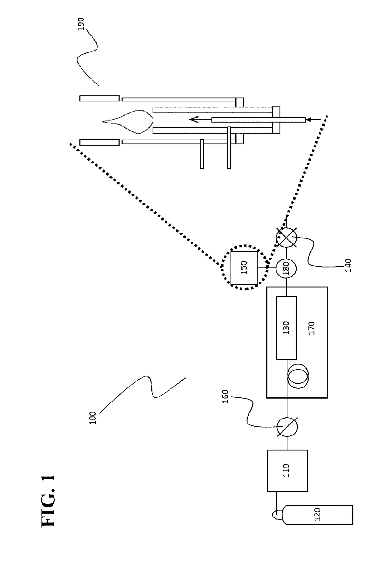
[0063]The analytical chromatographic system used was a carbon-dioxide based system (UPC2® System) commercially available from Waters Technologies Corporation, Milford, Mass., USA. The system included an autosampler, a column oven, a 3.0×100 mm ACQUITY UPC2 1.8 μm HSS C18 SB chromatographic column commercially available from Waters Technologies Corporation, Milford, Mass., USA, and an automated back pressure regulator. The mobile phase was 100% carbon dioxide supplied to the system via a fluid delivery module and was maintained at a pressure of 138 bar. The column was heated to a temperature of 45° C. The flow rate was 1.5 mL / min. The sample injection volume was 0.5 μL. At the outlet of the column, and upstream of the backpressure regulator, a “T” fitting directed a portion of the mobile phase flow to the BPR and a portion of the mobile phase flow to a FID (SRI Model 110 FID commercially available from SRI Instruments, Torrance, Calif., USA). The output signal of the FID was analyzed...


PUM

PropertyMeasurementUnit
angleaaaaaaaaaa
flow rateaaaaaaaaaa
flow ratesaaaaaaaaaa

Abstract

Burner assemblies are configured to deliver decompressed mobile phase of supercritical fluid chromatography systems to the flame of a flame-based detector while providing for improved optimization of analyte response as well as enhanced flame stability during operation.

Description

CROSS-REFERENCE TO RELATED APPLICATIONS[0001]This application claims the benefit of and priority to U.S. Provisional Application No. 61 / 994,353 entitled “Flame Ionization Detection Burner Assemblies for Use in Compressible Fluid-Based Chromatography Systems” filed May 16, 2014, which is incorporated herein by reference in its entirety.TECHNICAL FIELD[0002]The present disclosure relates to flame ionization detection burner assemblies and their use in compressible fluid-based chromatography systems.BACKGROUND[0003]Flame ionization detection (FID) was originally developed for use in conjunction with gas chromatography and is nominally designed to operate at relatively low mobile phase flow rates (i.e., up to around 40 mL / min). However, FID is now also commonly employed in conjunction with compressible fluid-based chromatography, hereinafter referred to as “CFC,” in which the mobile phase, typically compressed carbon dioxide, is used. An example of CFC is supercritical fluid chromatogra...

Claims


Application Information

Patent Timeline
Patent Type & Authority Patents(United States)
IPC IPC(8): F23D14/00G01N30/68B01D15/40
CPCG01N30/68F23D14/00F23D2206/00F23D2200/00B01D15/40
Inventor FOGWILL, MICHAEL O.MICHIENZI, JOSEPH D.MURPHY, JAMES P.
Owner WATERS TECH CORP
Why Eureka
Try Eureka